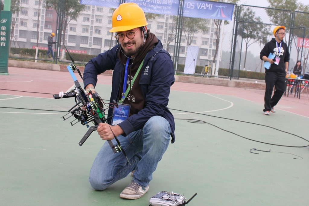
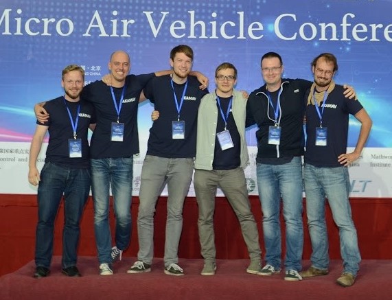
The AKAMAV is the proud winner of the IMAV 2016 Outdoor Challange. In this post we want to share the approaches, strategies and experiences we made in the past months.
Introduction
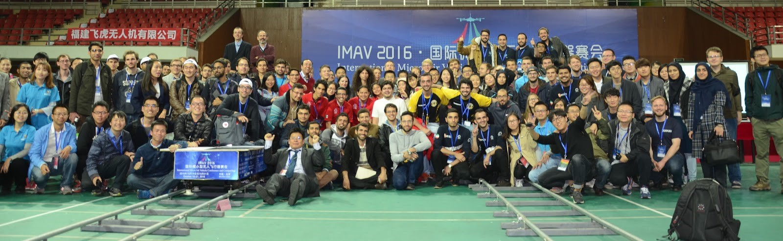
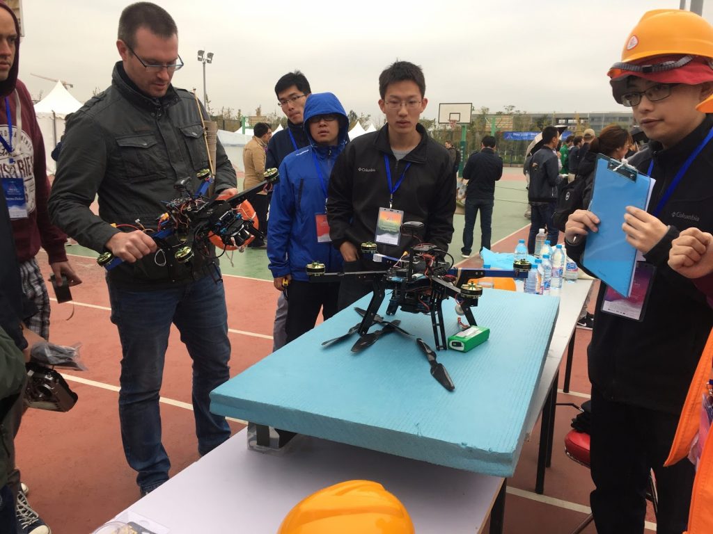
The IMAV (International Micro Air Vehicle Conference and Competition) is one of the biggest academic drone events these days. It’s hosted by a different university each year. 2016 was the first time it was hosted in China namely by the Beijing Institute of Technology. The amount of work and hospitality the organizing team put into this was one of a kind. Roughly 20 teams from all over the globe attended. If you share a remote interest in flying robots and don’t mind the occasional spectacular crash, this place was Disney Land on steroids with autonomous drones and Chinese noodles.
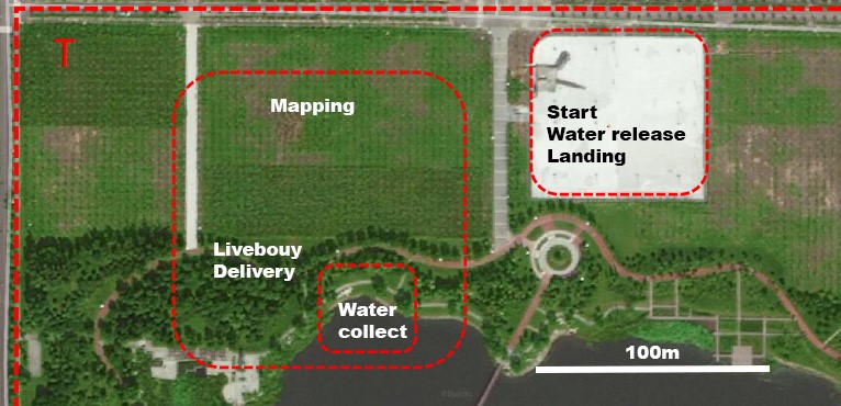
The competition was parted in an indoor and outdoor part. The goals of the missions were inspired by a hypothetical spill on an oil platform. To save the world from a horrendous hypothetical disaster, drones had to rush in and master the following missions:
Outdoor challenge:
- takeoff from moving platform
- live mapping mission area
- precise delivery of life buoy
- collecting and delivering of water sample
- landing on moving platform
Indoor challenge:
- takeoff from moving platform
- entering a building
- mapping the building
- picking up and releasing specific objects
- exiting the building
- landing on the platform
The complete rule set and all related information can be found here. In a nutshell: Each mission was scored depending on the achived difficulty level (e.g. landing on the moving vs. landing on the standing platform), depending on how small the vehicle was (smaller = better), how autonomous the mission was performed (no human interaction = happy judges) and how many missions were done in a single flight. Two vehicles could operate at the same time. FPV or LOS flying wasn’t permitted outdoors.
Approach
So how to prepare for 11 mission? Nothing you do on a weekend. We started roughly 6 months before the event by teaming up with TU Braunschweig’s Institute of Flight Guidance, identified missions which are also relevant for their work and created student thesis projects based on that. Still as always, most of the work happened in the last weeks before the event. Like last year, we focused on the outdoor missions. Most teams choose to concentrate either on the in or outdoor part, otherwise the amount of work would be sheer overwhelming. Yet we tried to solve indoor problems using FPV flying, because WHY NOT? In the last years we aimed for the simplest possible solution, this year we felt a little more adventurous and tried more sophisticated things: Some approaches were more successful than others. Read on for all our dirty secrets!
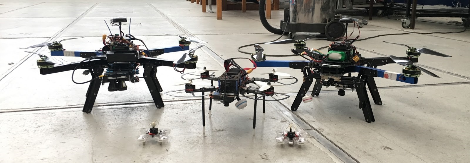
For the outdoor part two identical 550mm quads with 600g payload were used. As most teams we used the pixhawk autopilot with APM:Copter with an onboard companion PC. Noteworthy other components were a sonar for water pick up, a self designed PPP GPS receiver for precise delivery, lots of servos for dropping things, an IR-Lock infrared beacon for precision landing and a usb-camera on a servo gimbal for live mapping.
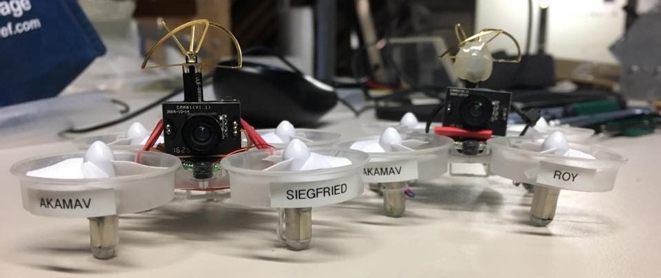
For the indoor part we used two 60mm TinyWhoops quads (For starting, entering and landing). If you haven’t flown one of these you haven’t seen the light my friend. For mapping and pick-and-release a 250mm modified fpv-racer was used. The mapping sensor was a 360° camera combined with Pix4D software.
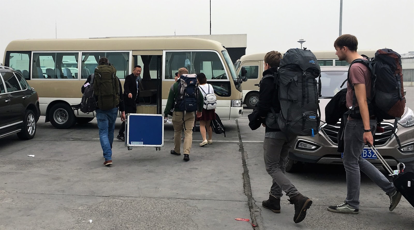
Traveling to China
Limiting to little equipment was new for us and tears were shed during the selections process, but it’s possible! We’ve chosen the capacity of our batteries according to most common airplane transportation guidelines to avoid problems (max. 100Wh batteries). If you want to import multiple custom build drones to china please get the export clearance and don’t do it the day before your flight (lessons learned). By doing so importing our equipment was not a problem. Some teams were not as lucky: Their equipment was seized by the Chinese customs and releasing it took several days. Pro tip: If you forgot your clearance, distribute your stuff on all people and don’t go through customs as a prominent group with flashy boxes. The biggest problem on side was getting a chinese SIM-Card (ignore anything but China Unicom shops).
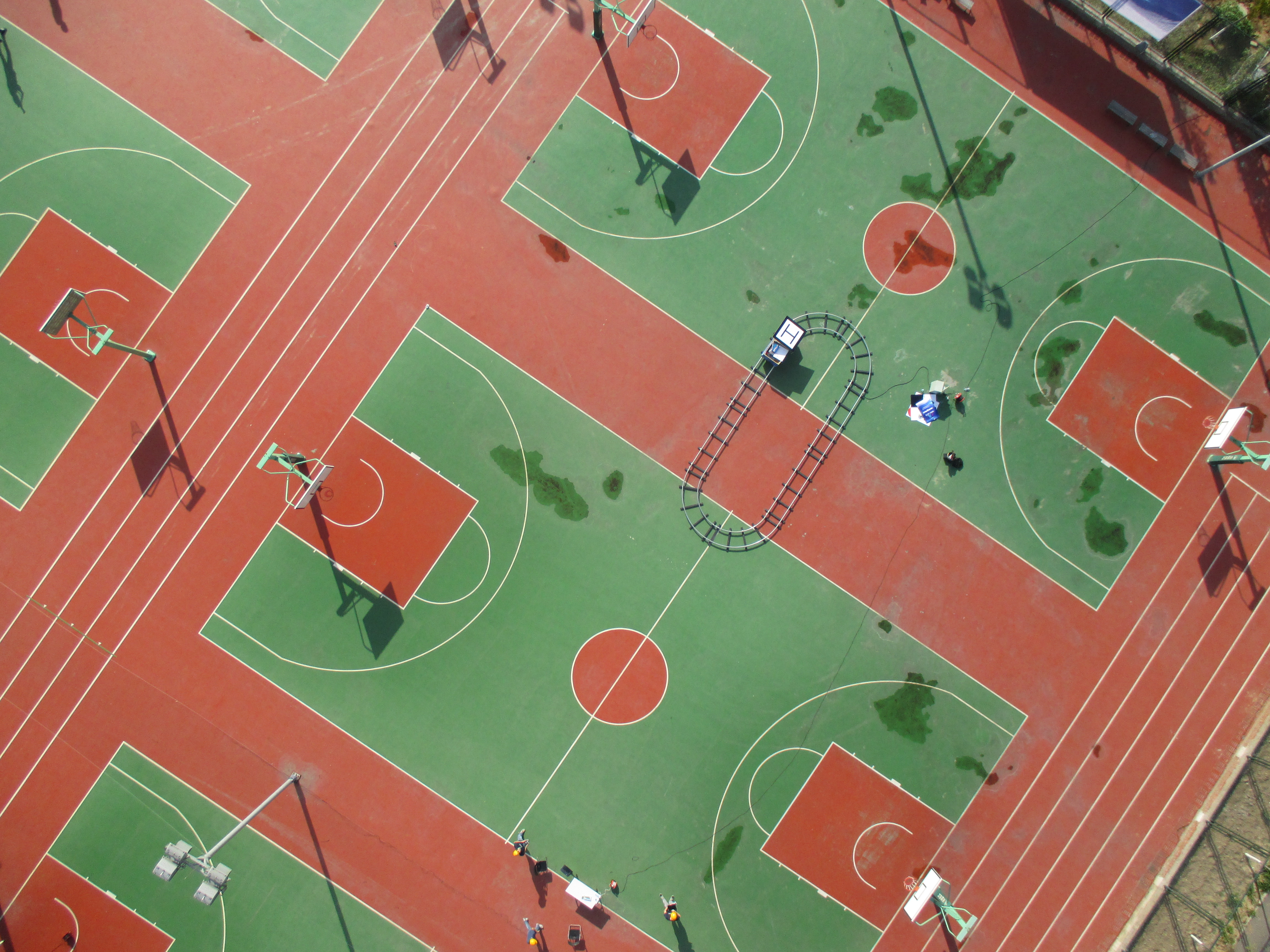
Outdoor Competition
The gods of satelite navigation will come to claim their sacrifice.
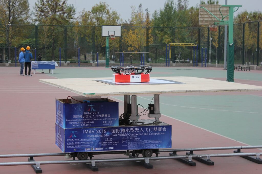
Takeoff Mission
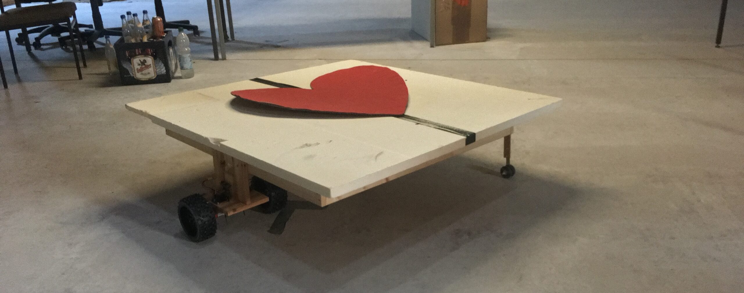
The first mission consisted of starting from a moving and rocking platform. On the basis of the competition rules we built a moving platform with the same dimensions for testing purposes. It was driven by two electromotors and controlled by an arduino. An extra rocking feature was not implemented because vibrations caused by rough underground appeared sufficient. We then used the moving platform for testing the takeoff sequence. Thereby we have learned two things: Firstly we performed the complete flight controller initialization sequence on a steady surface (no moving or rocking). Secondly, to make sure the MAV is taking off stable, we set the first waypoint which will be approached by the MAV above the centre of the circle in which the platform is moving, to increase the lateral stability during takeoff.
At the competition day we decided to take off from the moving non rocking platform which worked pretty good at the first attempt. Subsequently we tried starting from the moving and rocking platform which also worked fine.
Live Mapping Mission
The outdoor mapping mission was our „rabbit out of the hat“-trick to gather the last bit of extra effort to win the challenge. It was clear from the beginning that only a small amount of teams will have the time to implement and test a robust live mapping system, as the current state of the art does not provide a plug&play solution. One may ask why? Why is there no available solution for something so awesome, it allows you to overview a large area the second you fly over it? Good question, let’s hop in!
The Problem
The nature of real-time mapping involves at least the following components:
- UAV with camera (+ 2-axis gimbal stabilization),
- processing system,
- ground station,
- performant data link.
As this sounds like more or less the normal setup for offline map creation, a real-time capable system has high amounts of intercommunications, which makes a whole-in-one solution a difficult task. The camera snaps images every defined seconds, sends them to an on-board processor for further steps. Here you have to choose: Do I calculate the global map now, on-board with a waggon full of resources and take „sending out a growing global map“ as loss? Or do I reduce resources on the UAV, send out every image to the ground station, calculate a solution there and risk lost data packages on the way down? The perfect answer is: Yes!
The most time consuming part for generating high resolution maps live is the visualization. As current computer vision algorithms are rarely performed on full sized images the common approach is to resize the input images down to 20-30%. Afterwards the calculated transformation between input and global reference map is furthermore scaled back up to a wished value, which makes the process of transformation estimation quite performant and fast. However, the visualization does not benefit from those approaches as you have to finally iterate over all of your pixels to make them visible for the user. When using a 2 Megapixels camera that means 2 million iterations every defined second. That is hard to handle for regular desktop computers and even harder for embedded systems. It is therefore smart to leave the easy work for an embedded system on-board the UAV and do the visualization work with the whole processing power of the ground station. Benefit from that is, even though you lose any of the constant sized data packages (composed of image and transformation matrix) you have a global consistent solution still running on the UAV. That is especially great when dealing with a lot of radio interference on competitions. We therefore planned to fuse the two approaches into one, using the pro’s of both.
To curb your thrill of excitement at this point a little bit: We were not able to completely satisfy our goals on this one. The plan was to do the communication with LCM (Lightweight Communications and Marshalling), but in fact we lacked a proper long range wifi connection and time for robust handling. We ended up doing all the work on-board, which is okay for now, because it is only getting faster and better in the future. For a detailed look see our published conference paper.
As we were going for the real-time stitched map, we were also reaching for the stars aiming for the maximum points of 72 in this mission. When using classic approaches like offline photogrammetry without additional automation scripts other teams could only reach 18 points, which is a huge difference.
The Hardware
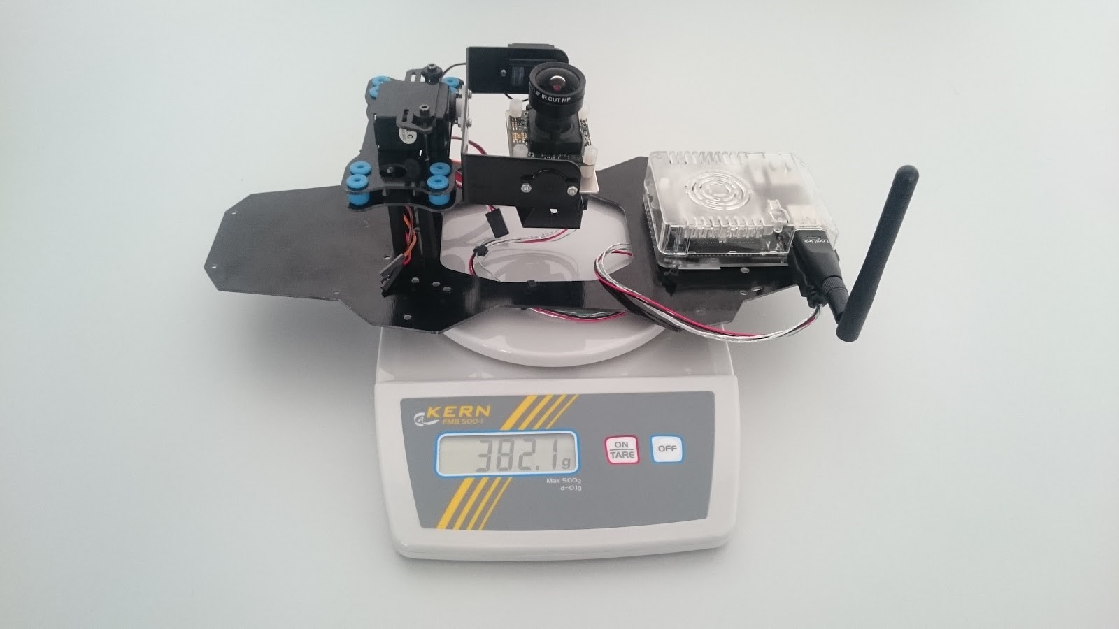
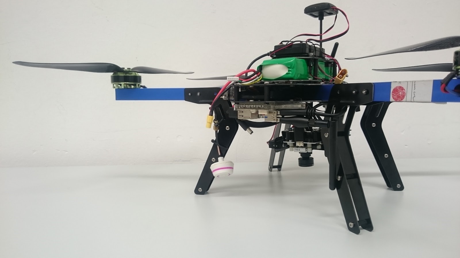
Below the mapping setup is displayed, weighing 382.1 grams in total. It consists of an UI-3251LE USB 3.0 camera sponsored by IDS Imaging Systems, a 2-axis servo gimbal stabilization and an Odroid XU4 with wifi dongle. Additionally as the wifi communication was not implemented yet, we connected a HDMI2AV-Converter (not in the picture) broadcasting the Ubuntu desktop of the Odroid via a FPV transmitter as analog video for the audience to fulfill the live streaming condition. The whole setup can be seen integrated into 1 of 2 our medium sized UAVs named Mausi the figure below. Mausi is based on an ArduCopter 3DR-D Quad kit with upgraded motors and 2.4 kg total take-off weight. It is able to fly 14 minutes and is controlled by a Pixhawk autopilot.
The Fall
During the first practice day setting up all relevant parameters of the stitching pipeline we experienced an odd flight behaviour. While in AUTO mode Mausi oscillated around the given GPS trajectory describing the path consequently but roughly. It seemed like the magnetometer had difficulties measuring the right heading or is at least getting influenced by disturbances. After recalibration it got slightly better, but was still vermiculating despite „okay-weather-conditions“. We decided to switch the GPS modules with our second, identical setup, that ran smoothly all day. While trying to remove the I2C plug from the Pixhawk the troubles took its course.
Despite the lovely handling and encouraging words the connector went out taking most of the solder pad with it. After various tries of resoldering we had to admit, that this Pixhawk has decided to not be part of this years IMAV. Here we were, 3 days left until the competition and 50% of our outdoor hardware broke. Good. Start.
The Recovery
After falling into a deep black hole of despair a glance of light appeared at the horizon. Our friends of the Beijing Institute of Technology mobilized all their resources to organize an exact copy of the Pixhawk we broke. On the other hand the electronic powerhouse of the polish Team JEDI decided to help a competitor in need, using all their solder skills to resurrect the dead. After replacing the Pixhawk and loading the backup parameter file (professional!) and calibrating everything, the copter flipped to one side after „take-off“. The problem was solved by resetting everything there is on the pixhawk. What sounds easy as pie is actually close to rocket science, as the Pixhawk tries to desperately save as many core settings as possible and defends them like a wolfmother. It was one day left when we got it running, allowing us to finally test the live mapping setup. Who needs sleep in the first place?
Competition day
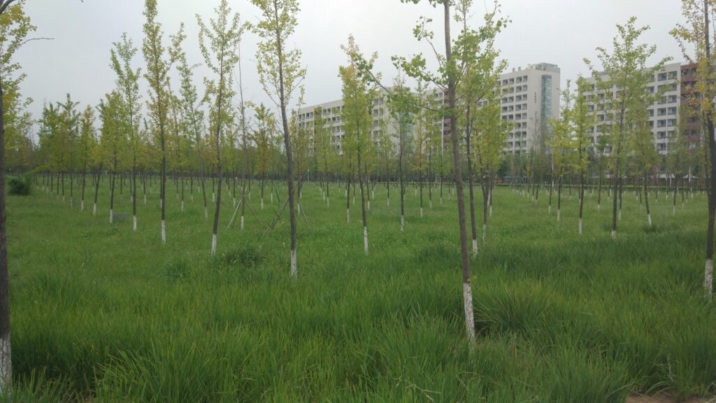
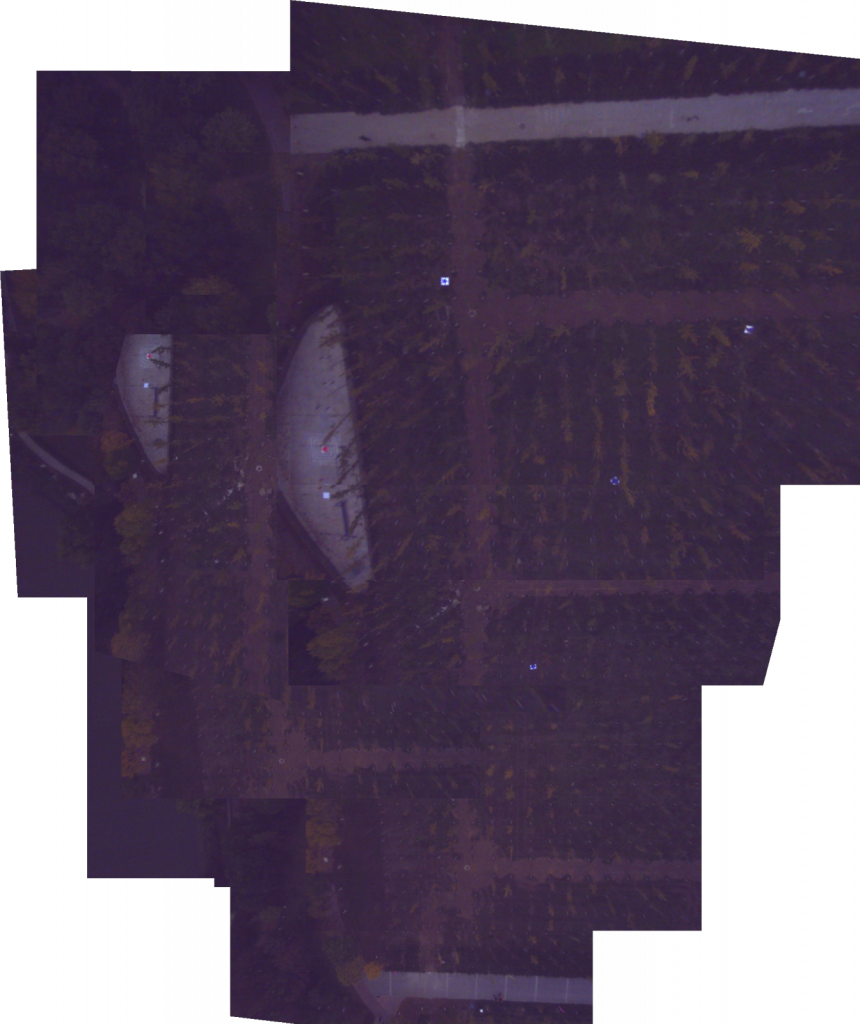
After intensive testing and 3 long hours of sleep it was clear: the mapping is going to be a gamble. The area to be mapped was dotted with small trees (see below). As the algorithm assumes the ground to be a plane every kind of perspective induced by objects is a risk of image misalignment. Additionally the position of the trees and the overall color is not unique, making it an ungrateful environment to realize an image feature based, naturally error-prone stitching pipeline. For situations like this, the implementation provides GPS-only based tracking capabilities to not lose the current position in the global map, even though an image transformation could not be calculated. To do so, the algorithm assumes that image centroid and GPS position are the same. Based on this assumption a scale from pixels to meters between two consecutive centroids can be calculated using the Haversine formula, simultaneously georeferencing the live mapping result. While this task is preferably done using Kalman filtering for sensor fusion, our code snippet was a last minute child of love featuring some ludicrous bugs. Nevertheless with the proud of a father and hope in our hearts, we dared to start the live mapping. And failed. When you decide to set the exposure time manually for more control in visually difficult environment (smog, bright concrete) you should definitely not forget to set it to a proper value at mission start…
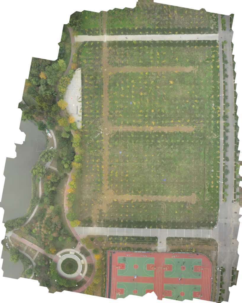
Luckily we structured our total time well enough to start an additional try in the second run. This time with worse lighting (later day, cloudier sky), better exposure time and an addon fall-back setup for offline mapping. Just in case. We succeeded somehow with a not so beautiful, yet real-time stitched map. Luckily there were no points for consistency of the result. In the end 5 out of 6 targets can be recognized making us one of few teams solving the live mapping mission at IMAV 2016. Cheers!
Delivery Mission
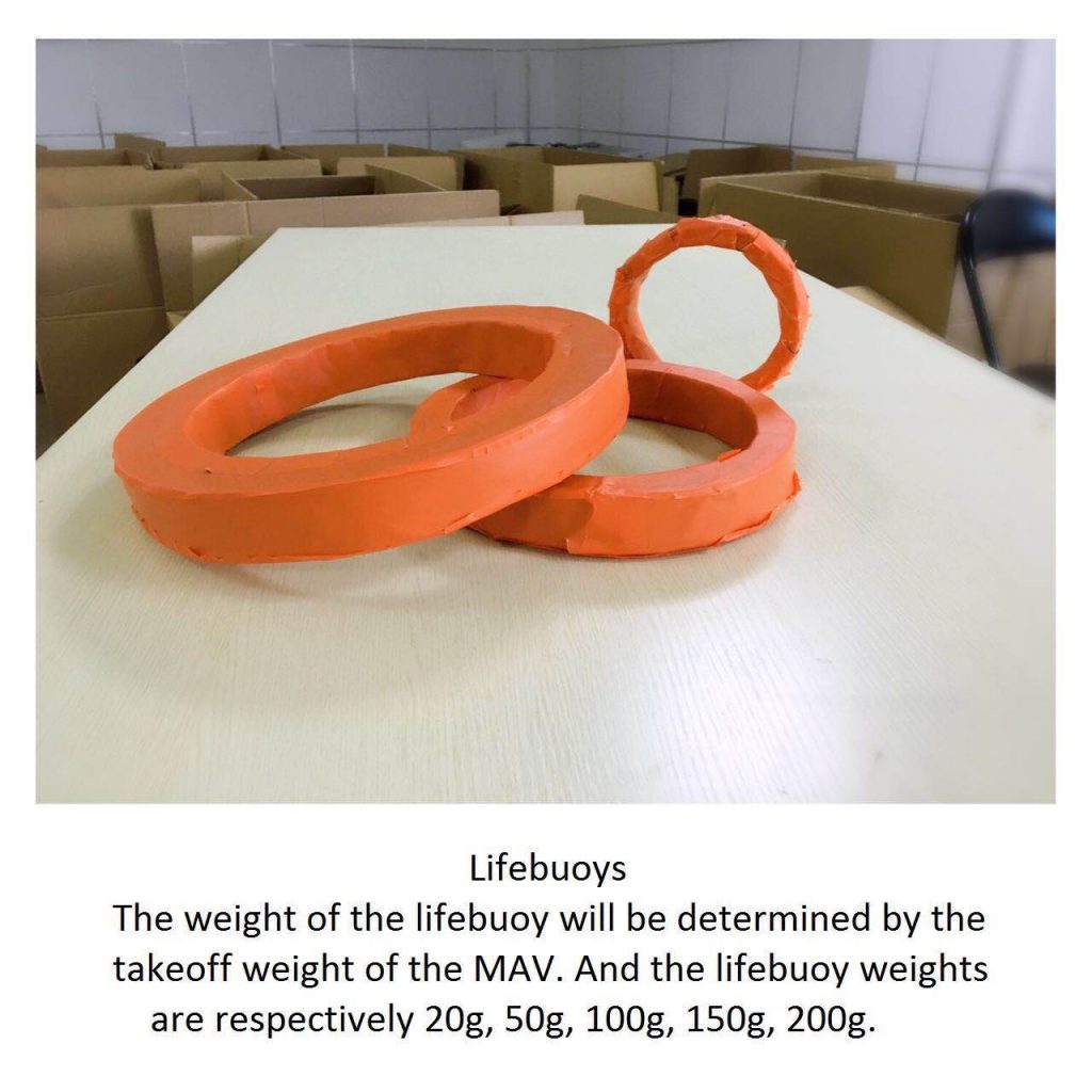
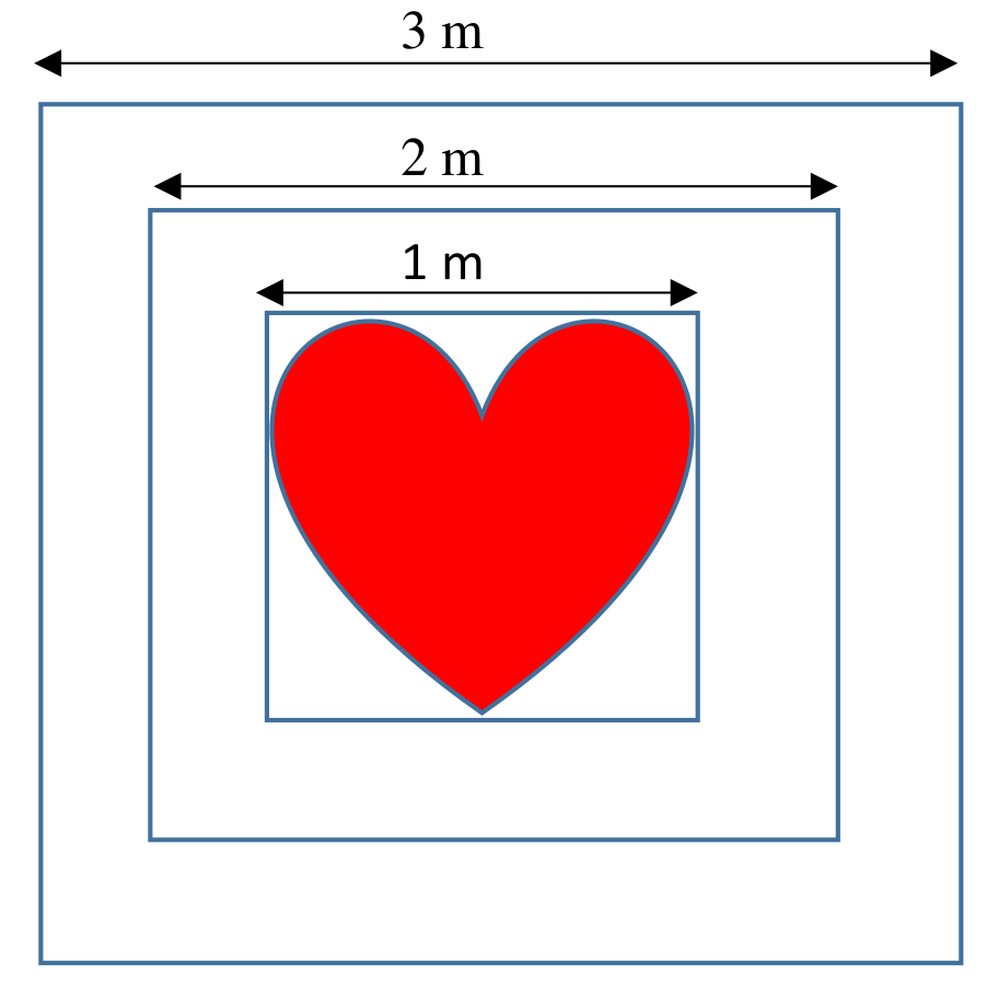
The delivery of the life buoy had a low barrier of entry in comparison to other missions like the mapping and was therefore an easy way to collect some points. But not completely without any challenges. The focus was on a precise delivery with only a small payload weighing less than 100 g. And this is where the trouble starts! How to achieve navigation with an accuracy way below 5 m? Below the life buoys and the given delivery zone for the life buoy during the competition are shown .
Initially our answer was to use a precise point positioning (PPP) GPS receiver, increasing the positioning accuracy in comparison to an ordinary GPS receiver down to some decimeters and enough to fulfill the mission requirements. At that time there was no PPP-GPS Receiver on the market, as a result we decided to develop and manufacture one on our own. As usual, it takes more time than expected and does not work on first attempt. Especially if you only have few experience with board designing. In consequence, the receiver was not working properly up to the competition. It found satellites but with a bad signal strength less than 30 dB. To achieve a GPS fix at least 4 satellites with a strength better than 35 dB are necessary.
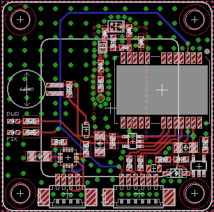
Our guess at the moment is that the antenna path is damping the incoming satellite signals. One of many design rules for PCB layouts working with high frequency signals says the following: don’t use right angles, otherwise the signal is distorted and damped, silly human! If you look at the PCB design shown in the figure above, what can you see in the antenna path? Yes, a right angle! And that seems to be one reason, why it is not working properly. We are investigating the layout more precisely and will update this page if we find out more. In the end we decided to discard this plan and go for the standard GPS receiver, being aware of the positioning gamble.
The strategy to release the life buoy was simpler and safer. We attached the payload with a small rope to a single servo, getting it dropped to the distinct position by an easy PWM trigger. The position of the delivery zone itself was given in Lat/Lon-coordinates during the competition day by the judges. To reduce the risk of losing the GPS fix in the drop zone, we decided to deliver the life buoy at a height of 6 m, avoiding signal shading by the trees in the near surrounding.
Luckily differential GPS (DGPS) was available which increased the positioning accuracy a little bit. At our first attempt the MAV hit the 3 m circle of the delivery zone, which is really great with the described setup.
Water Sampling Mission
The main requirement for the water sampling mission was also set to a precise navigation. With only 20 ml total water volume the weight of the probe was negligible. However to achieve the demanded positioning accuracy for our initial design we decided to go for a really sophisticated approach. Our chosen strategy can be distinguished into the following steps:
- Take off
- Fly to the water collecting zone in a distinct height
- Unwind a bottle
- Take a water probe
- Rewind the bottle
- Fly back to the water dropping zone
- Drop the water probe
- Land
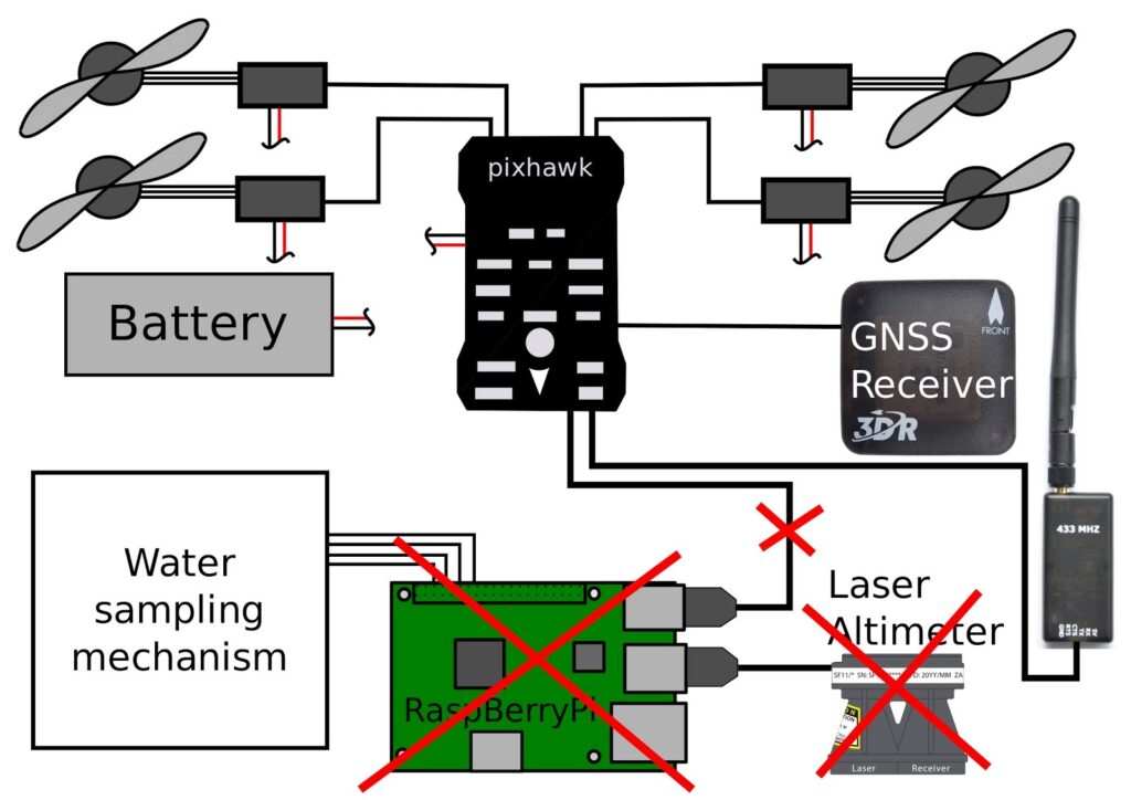
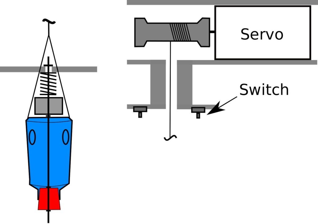
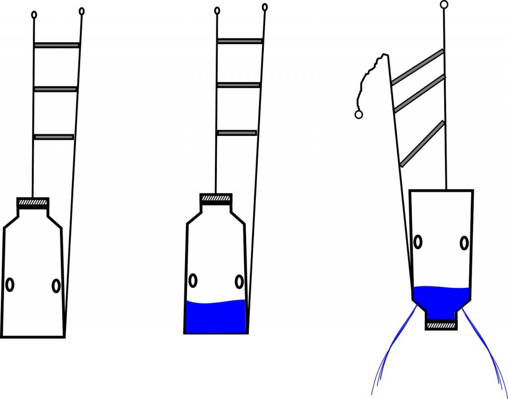
The figure further down shows the general system structure. Parts striked through were part of the initial design, but were removed during testing. To operate the water sampling mechanism a Raspberry Pi single board computer (SBC) was used. The communication link between the pixhawk autopilot and the SBC was established via MavLink over USB. To Measure the height we planned to use a LightWare LiDaR which is more precise than a barometer and capable to measure distances up to 130m. The detailed water sampling mechanism is depicted in figure below. The total weight of the mechanism is 313g.
To unwind and rewind the bottle, a digital high torque servo was used. The bottle can be filled with water over the site holes. To release the water probe the bottle will be pull up till the limit stop switch is triggered. By increasing the torque again the spring will be compressed up to the plug is pushed out. The communication link between autopilot and SBC was needed to trigger the SBC at the right time to perform the described sequence. For example at a distinct GPS position and height.
Nevertheless the described release mechanism worked, at least the mechanical part was working. All along the weak spot was the communication link between the autopilot and the RaspBerry Pi. And here the real story begins. We started the integration phase only one and a half week before the competition. As was expected the time ran over and the communication link was not working properly. Unfortunately the servo gave up working during integration. Additionally the design of the driver for the wind was crude and too complex. Arrived in china, we gave it a last chance for one test. But also the final test was unsuccessful, by still unknown reasons.
Up to the last minute
We had a self-given deadline until which solutions had to work or they were replaced. Sadly the communication link to the winch based water sampling didn’t work until this date. In consequence we dropped it and went back to a simple servo-drops-something solution. But what shall it drop?
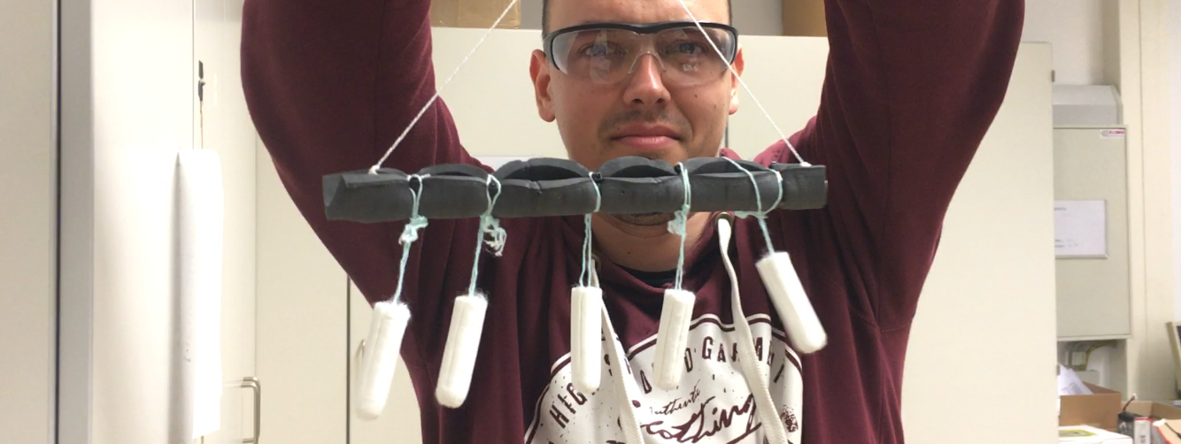
To speed up the whole process, we made up a small challenge. We build up three different mechanisms and chose the best. You can see the result of the challenge on the figure below:
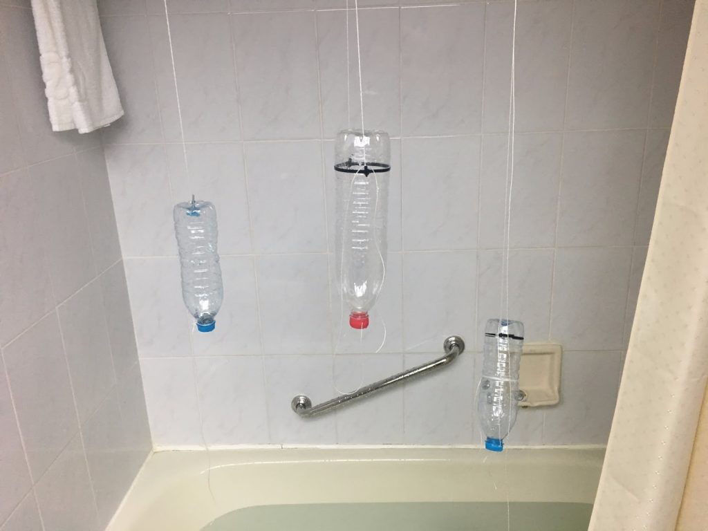
The idea of the final design was as following. Take a bottle with fill in holes at the center of the bottle and attach two ropes to the bottle, one at the neck and the other at the bottom. Both ropes are fixed by a single servo at the MAV and can be released independently. In comparison to the initial design we had no wind. Thus the problem was that waypoints underneath 0 m can not be approached by the autopilot, so there were approximately 6 m of rope attached underneath the UAV to compensate air pressure fluctuations. The smallest squall is sufficient and the whole thing starts turning. Therefore we attached chopsticks in the same distances to each other, to avoid unintentional twisting of the ropes. To drop water the rope attached to the neck of the bottle will be released first, as shown in the figure above.
We were not sure to meet the dropping zone exactly. Even though to reach the water tank we attached small holes at the neck of the bottle which peformed like a shower head.
Lessons learned
Even though finally the initial design was not working it was a great experience and we have learned a lot. The most we have learned is that a complex system takes at least 20 percent of the scheduled time only for integration. So start on time!
Platform Landing Mission
In the early design phase we decided to use the pixy cam with an associated IR beacon for precision landing, because of the easy integration in the pixhawk autopilot system. The whole computer vision process is directly done on the PixyCam and you don’t have to think about it. The connection between autopilot and PixyCam was established via I²C. Basicly the sideways divergences to the target will be transmitted and handled by the autopilot. The camera is equipped with an IR filter to prevent visible light interferences. In addition the IR beacon emits a specific LED pattern at a distinct frequency increasing the redundancy all the more. As the initial approach we attached the pixy cam with a gimbal under the MAV. However the achieved results were even worse the direct mounted cam. Therefore we attached the camera without any gimbal directly under the MAV, which worked pretty good.
The precision land was tested on static and moving targets. Tests resulted that the MAV is following a moving target up to 1 m/s ground speed. At higher speeds the IR beacon is moving too fast out of the field of view of the pixy cam and the MAV loses the track. On static targets we reached a precision between to 5 to 10 cm.
At that point we realized it was too challenging to implement a precision land on a moving platform with the chosen sensor, so we decided to approach at the competition the land only on a static platform.
To get a more precise view of the capabilities of the sensor we build up a simple debugging tool, to observe the status of the camera during flight, to get to know if the beacon is in the field of view or not. Therefore we took advantage of a simple status LED on the camera module. The LED was performing exactly what we need, but sadly too dark. So without further ado we placed a big LED array, to ensure visibility from the ground. Mostly we were interested in the field of view and the resulting recognition range for better path planning later on. In general the autopilot is processing the measured sideways distances as soons as the the MAV is in land mode and is performing from there a precision land. Which means the last waypoint, before land, should be near to the beacon. The results of the tests revealed that the camera reliable recognize the beacon in a height up to 12 m and a radius of 3 – 4 m.
Well prepared for the competition, we performed on the competition day a precision land on the static platform at the first try.
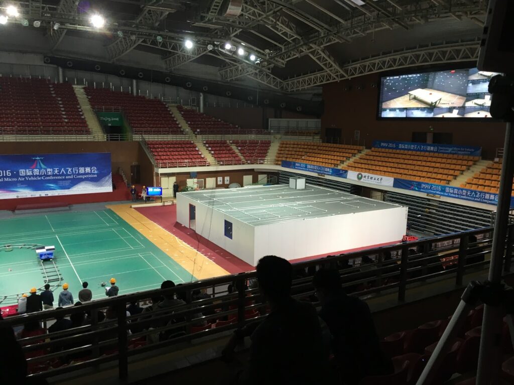
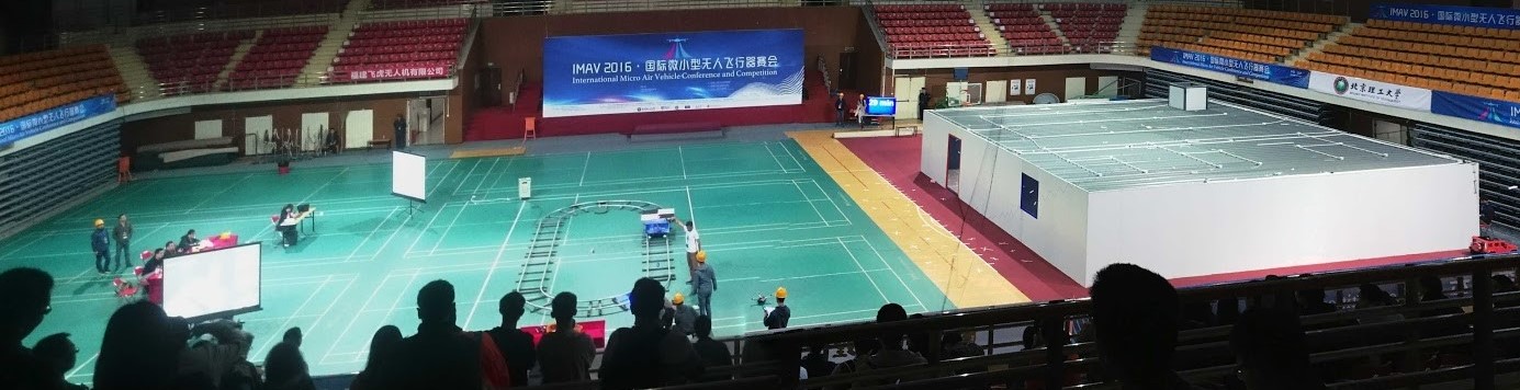
Indoor Competition
The indoor part took place in BIT’s indoor sport arena. A one story building with 4 rooms, one door, one window and one chimney was set up, the missions were
- takeoff from moving platform
- entering a building
- mapping the building
- picking up and releasing specific objects
- exiting the building
- landing on the platform
Entering Building Mission
Unlike the outdoor part, FPV flight was (still?) allowed indoors. We choose to fly everything FPV since the implementing of a robust LiDAR or Vision based navigation would have been too time consuming. Takeoff, entering, exiting and Landing on the plattform was done using a TinyWhoop FPV Copter. Due to the size of only a few Centimeter the size factor was high and we were able to master all the planned tasks on the first flight without any problems. The original FPV footage can be seen on youtube.
Pick and Release Mission
A solution for picking up and releasing the small buckets was realized using a modified 250mm FPV racer. The vehicle was equipped with propeller protection to minimize the impact of contact with walls etc. A servo controlled „lance“ was mounted in front of the FPV camera in order to pick and release the pucket. Initial tests showed that the collecting of the bucket was hard due to its location on a table. The downwash of the approaching copter would interfere with the table surface right before the copter would reach the bucket. This situation impeded the manual altitude control heavily making it really hard to hit the small target with the lance. The attempt to solve this using a downward facing ultrasound sensor were not successful due to difficulties in tuning the altitude control loop on short notice.
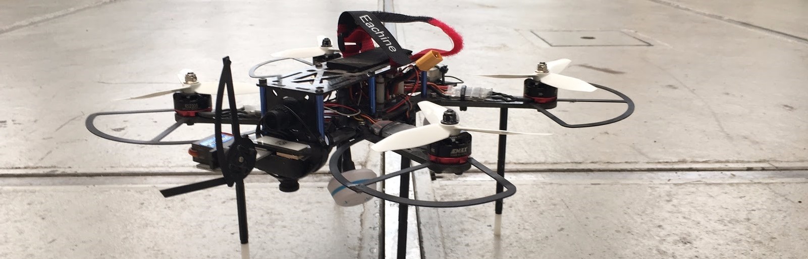
Therefor the landing gear was extended to a length which allowed the copter to land in front of the bucket and pick it up using the lance once the servo was triggered. When the vehicle hovered over the target area, the bucket would be dropped using the servo. Aiming was realized using a second FPV camera/transmitter combo. A Copilot was then needed to guide the pilot. While the bucket collecting and releasing worked under good conditions in our lab it didn’t on the test side. The available space for landing the copter on the table was so small that every small error caused the copter to hit an object, causing a crash. Yet no other team managed to do this either.
We lost a lot of landing gear in these crashes. Luckily we found a greatly available resource for replacement: chopsticks!
360° Mapping Mission
The indoor mapping mission was another challenging task. The tasks stated that 3 unknown rooms had to be mapped. Most points were given when the created map was in 3D and the furniture in each room recognisable.
Since we had little expierience using LiDAR or optical SLAM algorithms we decided to use offline photogrammetry for mapping. We had good results using commercial software like Agisoft and Pix4D in outdoor scenarios and wanted to use these idoor too. UAV based photogrammetry is a little tricky indoor, since you need to plan your flight more carefully to garantee the needed overlap in every image. Spheric (also known as 360°) cameras seemed like a clever solution to garantee this overlap while recording the room in any angle (no missing information). Pix4D also started supporting 360° images and named the Ricoh Theta S as the lightest supported camera, which we therefore used. We mounted the camera on the 250mm racing quad and started testing.
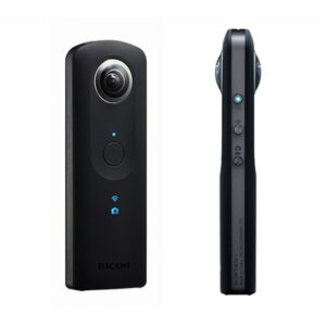
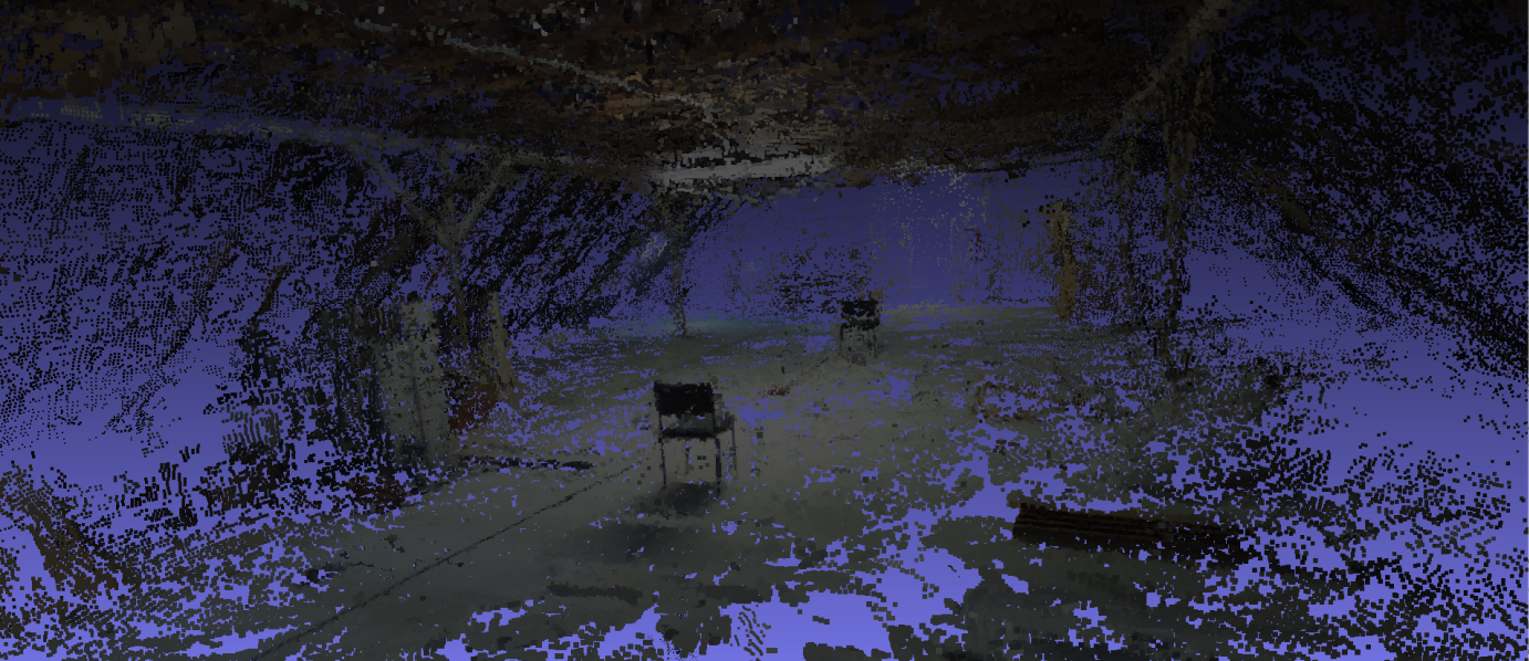
The camera can be controlled with a smartphone app and many settings can be set manually. The camera produces good spheric images and videos without any additional processing. The biggest drawback is the limited final resolution (Video 2MP / Photo 14MP). The created images and videos looked stunning, this technology is here to stay. The results from our mapping approaches were also good, IF the conditions were good. The image displays a dense cloud created with Pix4D using 360° images on the attic of the IFF. You can also see the 3D point cloud on sketchfab.
The software was able to create good results when all of the following criteria were fullfilled:
- a lot of overlap (like ~10 images per room or every ~0.5m)
- a lot of features (no regular white walls etc.)
- enough light (beware of neon light frequency induced artefacts)
- static scene (try to hide behind the camera… oh!)
When any of these criteria weren’t met Pix4D wasn’t able to align the images. In the current state, the workflow is much more sensible regarding these disturbances compared to „regular“ images, therefore the use of 360° cameras didn’t really simplify the process.
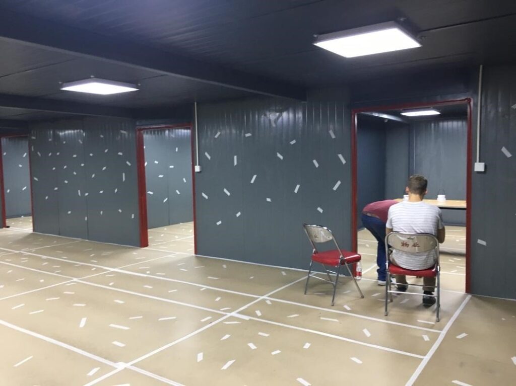
For mapping the camera was put in interval shooting mode (one image every 8 seconds at full resolution) while the vehicle was slowly flown through the rooms using FPV. The processing took about 15min (using low quality settings). Sadly the mapping did not work in the rooms prepared for the IMAV indoor competition. The main reason beeing the lack of features. While the walls were covered with bits of tape, this was not enough. Also, the walls of the building were very sleek, which lead to always changing reflections of the light sources. This 3D point cloud was the successfull result we got during the test day.
Final words
We learned a lot in the weeks leading to this event and hope we were able to pass on some of our insights. Team AKAMAV will be in Toulouse at IMAV 2017 to meet all of you wonderful nerds. We are always curious to meet new people! If you are a student, drone enthusiast or professional who wants to contribute, learn or simply geek around with us, please come! We have much more ideas then time on our hand.
Outdoor Competition Scores
- AKAMAV, Germany 279.7
- ISAE, France 225.6
- SCV, Korea 205.7
- AUTMAV, Iran 167.4
- FanSO, China 155.3
- JEDI SG, Poland 84.4
- MRL-QIAU, Iran 84.0
- BlackBee, Brazil 63.6
- MAVLab, the Netherlands 57.6
- Cigogne, France 46.2
Indoor Competition Scores
- KN2C, Iran 423.9
- Quetzalcuauhtli, Mexico 361.7
- MAVLab, the Netherlands 271.1
- CVG-UPM, Spain 268.1
- JEDI SG, Poland 253.1
- ARC, Iran 218.3
- AUTMAV, Iran 198.6
- UI-AI, Iran 81.2
- AKAMAV, Germany 43.8
- MRL-QIAU, Iran 21.8
- Persian Gulf, Iran 20.9
- BlackBee, Brazil 0
- EuroAvionic, Poland 0
Last but definitely not least we want to thank all of our sponsors, namely the Institute of Flight Guidance, TU Braunschweig, GOM GmbH, IDS Imaging Development Systems GmbH and u-blox Holding AG. A special thanks goes out to our team leader Mario Gäbel for doing so much development work and still being able to manage and organize our tour and financial paperwork. Also a big shout out to the rest of the team, namely: Benjamin Hülsen for rock-solid electronic layouts, Dimitri Zhukov for unbreakable constructions, Alexander Kern for computer vision that never stops tracking, Endres Kathe for not marrying an Arduino and Markus Bobbe for destroying only one of our Pixhawks.
Happy Flying!