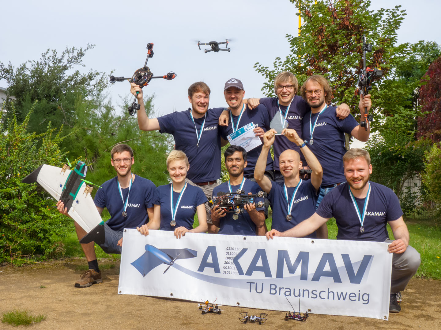
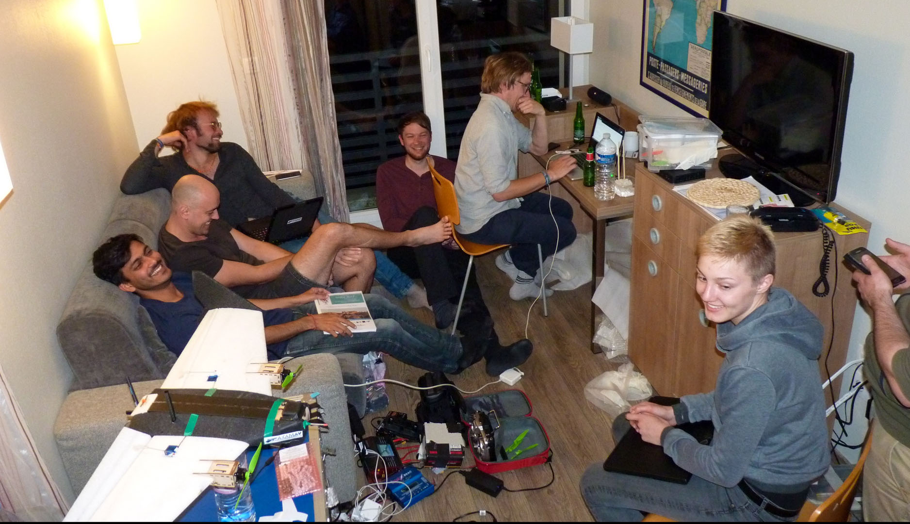
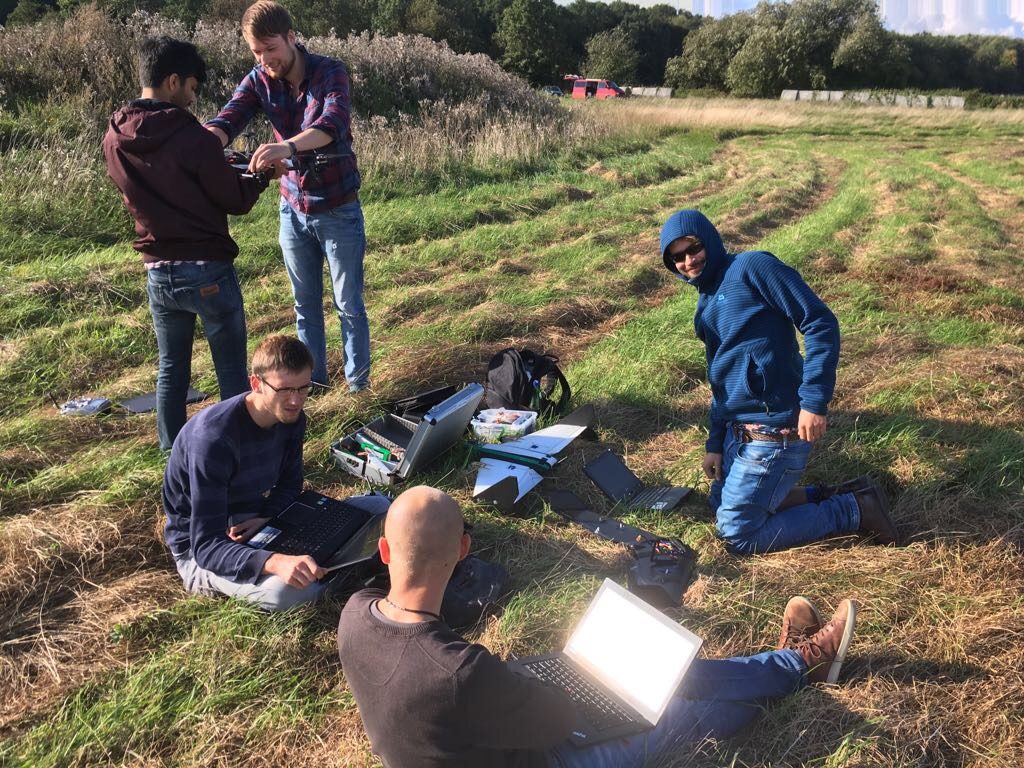
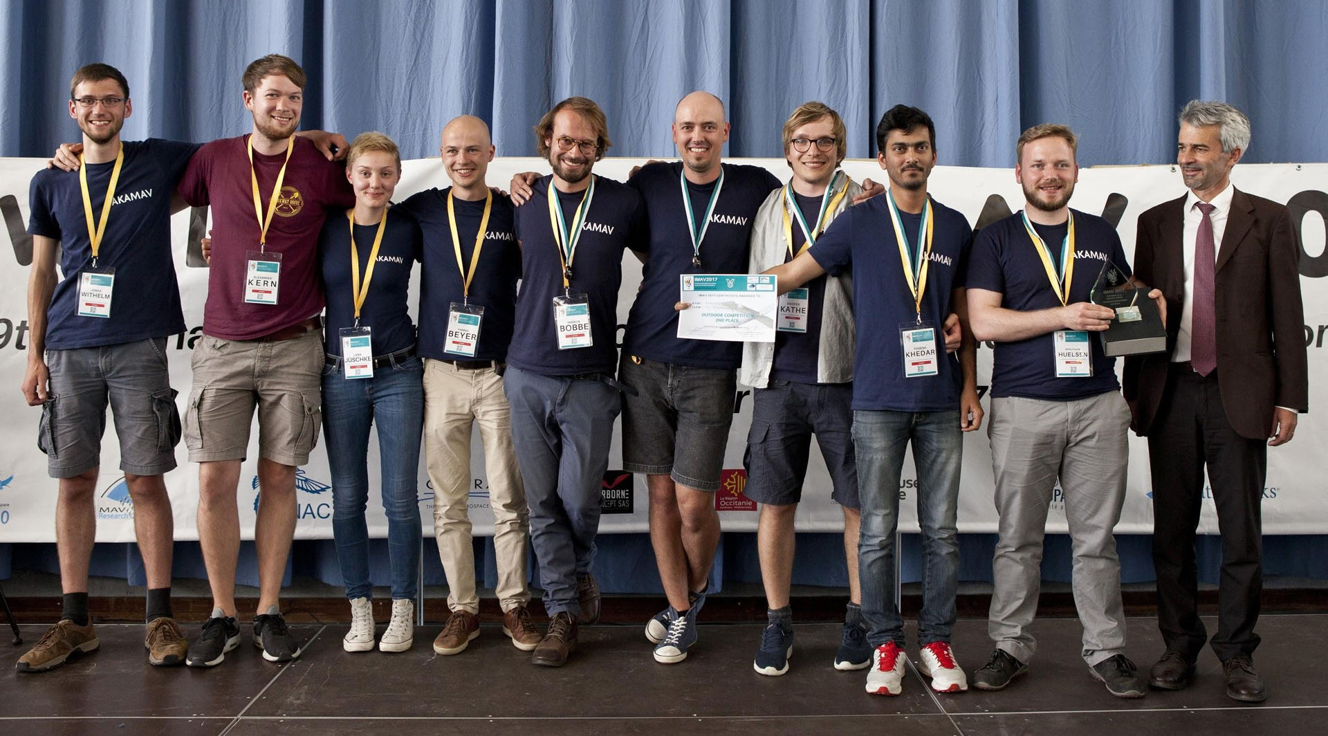
The student group AKAMAV of TU Braunschweig achieved 2nd place in the IMAV 2017 outdoor competition. We had a really incredible week in Toulouse. This is the place where we want to share our insights, experiences and most importantly the many mistakes we made during our journey through the land of drones!
Introduction
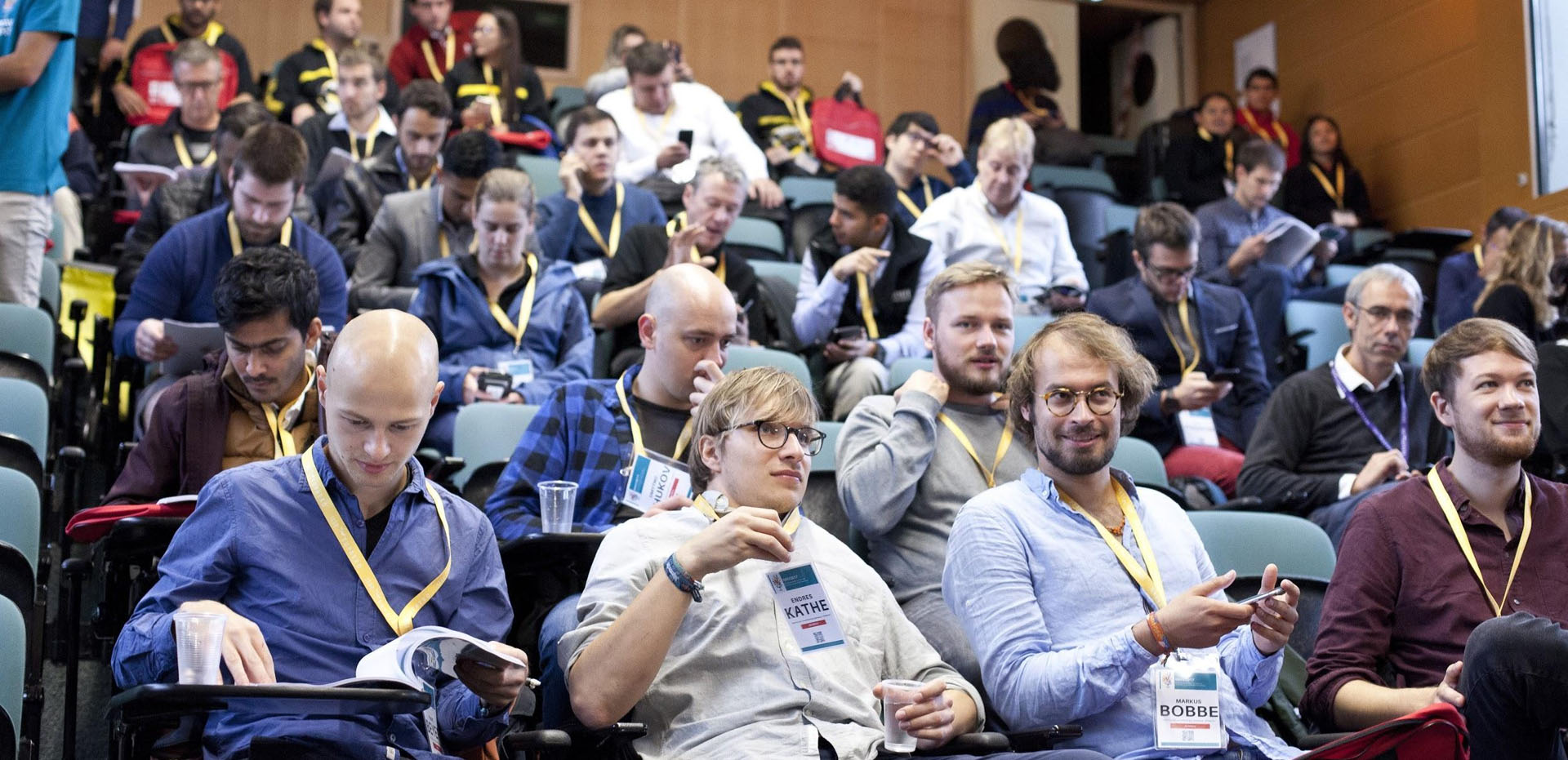
The IMAV (International Micro Air Vehicle Conference and Competition) is one of the biggest academic drone events worldwide. It is hosted by a different university each year. In September 2017 it was hosted in France namely in the heart of French aerospace industry in Metropole Toulouse in ISAE Supaero Institut. The amount of work and hospitality the organizing team put into this was only rivaled by the beauty of late summer in France. Roughly 20 teams from all over the globe attended. If you feel anything when you hear the word drone, your endorphins would’ve been running wild in a week full of drone talks, races and crashes.
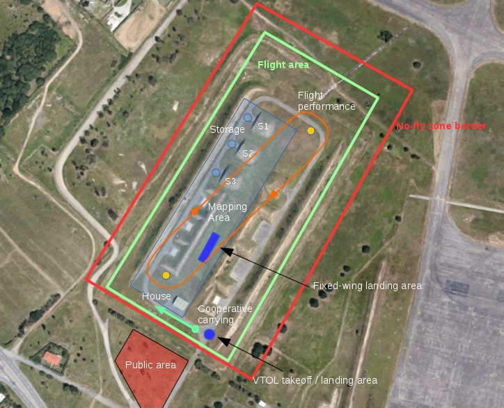
The competition was divided in an indoor and an outdoor part. The goals of the missions were inspired by a hypothetical fire disaster in airport surroundings. To save the world from a horrendous hypothetical disaster, drones had to rush in and master the following missions:
Outdoor challenge:
- Automatic take-off
- Flight performance
- Mapping
- Target detection
- Cooperative carrying
- Landing
Indoor challenge:
- Take-off
- Flying through the window
- Flying through the “obstacles” zone
- target detection and recognition
- Drop zone
- Cooperative carrying
- Precision landing
Special jury challenges:
- Virtual challenge (in MATLAB/SIMULINK)
- Treasure hunt challenge (detection of metal obstacles in the ground)
- Drone team parade trophy (three or more drones performing a cooperative flight)
- Record breaking session (small drones are carrying heavy things )
The complete rule set and all related information can be found here. In a nutshell: Each mission was scored depending on the level of achievement (e.g. number of detected targets), depending on how small the vehicle was (smaller = better), how autonomous the mission was performed (no human piloting = more points for human) and how many missions were done in a single flight. Multiple vehicles could operate at the same time. FPV and manual flight using a remote controller was not awarded in any way (sorry FPV people).
1.1 Approach
This time AKAMAV-Team concentrate its resources on the Outdoor missions. Preparations startet about 6 months before the event with the friendly folks from Institute of Flight Guidance of TU Braunschweig. Also as always, people get really busy in the weeks before the deadline. Most teams choose to concentrate either on the indoor or outdoor part. Otherwise the amount of work would be sheer overwhelming.
After the initial strategic meeting four (sub)teams were formed.
- Team Flight Performance tackled the endurance mission with a hybrid
- Team Mapping did the missions take-off, mapping, detection and landing
- Team Cooperate Carrying did exactly that
- Team Treasure Hunt …you get the point
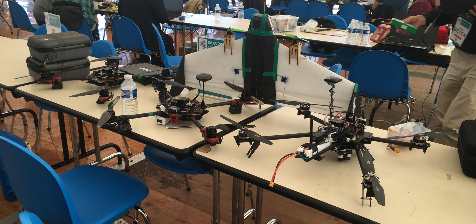
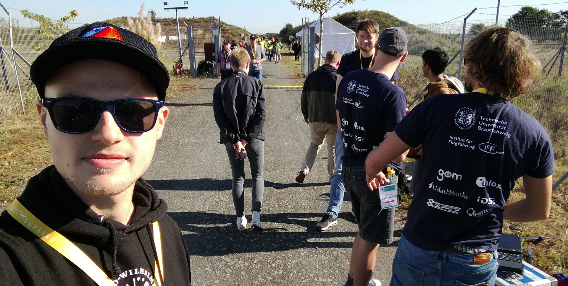
All missions were done using the gear displayed above. 2 strap-down „dump“ 850 mm quads for cooperative carrying, one „smart“ Odroid equipped 590mm frame quad for mapping, one hybrid Flywing Akbird for endurance and a back-up DJI Mavic when everything else is on fire. The following article is structured by using the topics and sequence of the four teams given above. Ladies and gentlemen, please fasten your seatbelts the captain has switched on the nerd-shit sign…
Flight Performance
| Role | Name | |
| Team Captain | Yannic Beyer | y.beyer[at]tu-braunschweig.de |
| Pilot | Jonas Withelm | j.withelm[at]tu-braunschweig.de |
Let’s build a VTOL (Vertical Take Off and Landing)!
In the flight performance mission, the goal was to fly as many laps as possible within the time slot of 15 min and land before(!) the time is up. The points for this mission were basically calculated as follows: Number of laps divided by size of vehicle.
An additional challenge were GeoFences that required a shutdown of all motors if the virtual competition border was crossed. The maximum flight altitude was only 30m. Yeaah right? Both, hand launch and belly landing were allowed. Hence a VTOL did not really provide extra points, but who thinks rational if you can build a VTOL?
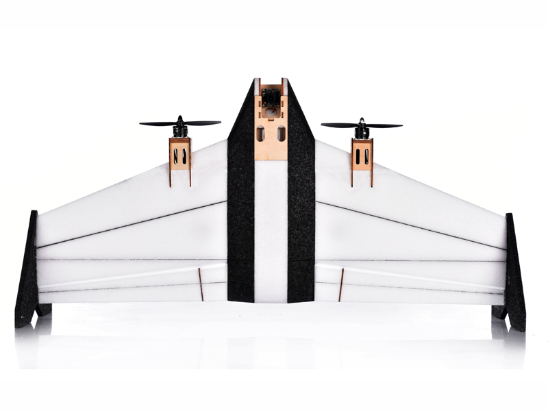
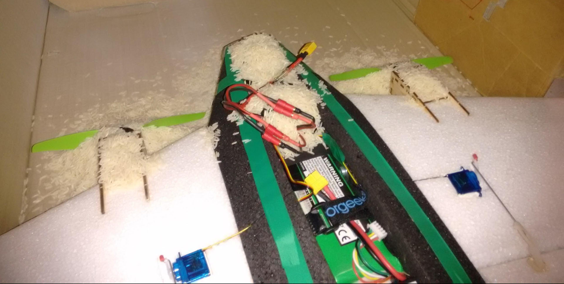
First step: Choose a VTOL. There are several configurations. A simple and elegant VTOL concept is a tailsitter flying wing. This configuration needs no additional motors and no tilt mechanisms. Moreover, a flying wing seems to be an efficient aircraft configuration as it has no fuselage and no tailplane. Thus, it produces less drag. One good, cheap and crash-tolerant foam frame is the Arkbird (figure 1). The body costs only $99 from your favorite chinese warehouse.
However, as VTOL MAVs are still very new, there were several problems setting up the tailsitter flying wing. Hence, the following guide might save you same days if you are working on a similar project.
2.1 The Aircraft System
As already stated, we decided to try our best with the Arkbird frame to get him fly like an eagle. For the remaining hardware parts we decided to use the well known Pixhawk autopilot hardware platform which would allow us to test various flight controller firmwares.
Hardware
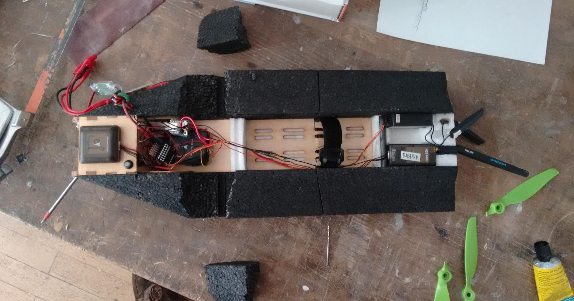
In addition to the Arkbird frame, we still needed a pair of motors, ESCs, servos and some sensors to measure the flight state. For autonomous navigation you need at least a GNSS Receiver (with a magnetometer) and for planes it’s also very helpful to use a Pitot-static tube to measure the airspeed. For the really interested minds who want to know the deep hardware specs to build a similar setup, we put all the important configuration parameters together and you can find them in our Git.
In other respects, we have not modified the Arkbird-Kit too much. We only glued some drive-in nuts at both ends of the wings so that it would be possible to disassemble the whole thing for transporting reasons. The figure above shows a photo of the final VTOL.
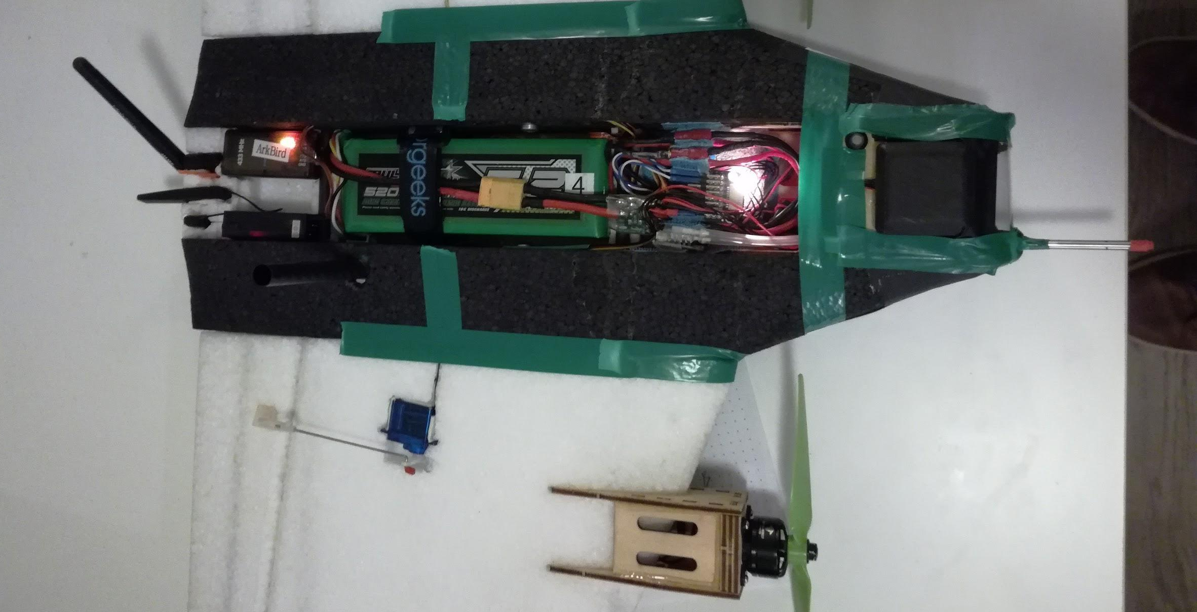
In our setup, the flight controller was placed parallel to the wings. The total mass is about 1.1 kg, the Center of Gravity (CG) position is about 10 cm behind the inner leading edge of the wings.
An appropriate CG position is one of the main problems of flying wings. If the CG position is too close to the rear, the flight dynamics become unstable or even uncontrollable. If the CG position is too close to the front, (large) permanent elevon deflections are required which reduce the efficiency and the aircraft becomes very sluggish in terms of pitch reaction. The critical CG position can be estimated with aid of the following figure and formula. If the CG is behind the critical CG position, the flight dynamics are unstable. Usually, you want to choose a CG position that is slightly in front of the critical CG position. Note that the critical CG position according to the formula tends to be smaller than the true critical CG position. Consequently, this procedure usually protects you from becoming unstable accidentally. The aerodynamic influence of the fuselage is neglected.
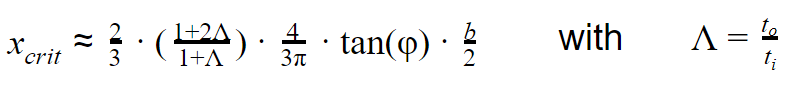

In our case, the critical CG position is about x_crit = 5.3 cm and the actual CG position is about x = 5 cm.
Firmware
There are multiple open source firmwares available like PX4, ArduPilot and Paparazzi. For our project we tried out PX4 and ArduPilot (ArduPlane). PX4 supports the tailsitter configuration for more than one year. It includes a blending strategy in between hover and the cruise mode which is supposed to improve the flight dynamics during the transition phase. ArduPlane started supporting the tailsitter configuration early in 2017. At the moment it just switches between the hover mode and the cruise mode instantly without a transition phase, which looks like the Arkbird is firing a rocket booster to get as fast as possible in the horizontal attitude. For the reason that the ArduPlane firmware was technically less sophisticated in this area than the PX4 firmware, we decided to try out the PX4 firmware 1.6.5 dev (git Revision: 3098c77c9168553c) at our first attempt.
We spent some days to set up the parameters according to this post. We felt slightly uncomfortable because it seems that the user does not have control about all parameters. For instance, the servo signal wiring and multiple controller gains do not seem to exist. Moreover, we spent several days with flight test without successful transition phases. After enabling the forward transition mode the aircraft began to lose control about the roll axis and did then start to intensively oscillate in the pitch axis. Separately, both the hover and the cruise mode worked fine and stable, despite of some minor problems like slightly unstable descending in hover mode. We tried to adjust the parameters for the blended transition phase, however, it seemed, that they did not have any effect. To explain the problem in detail, we were not able to get the blending of the two different control loops (Vertical Take Off and Cruise) to work properly. In this way the huge aileron deflection which is necessary for the Vertical Take Off was way too much for the forward flying plane. Unfortunately, because of the not working blending phase, it was used for the whole transition phase causing the plane start with the already described oscillating movement. After two rather depressing weeks, we concluded that the firmware must have a bug and decided to try out ArduPlane, rather than testing the newest commit of PX4.
Using ArduPlane it took us exactly two days to do some first successful flight tests including very reliable transitions forward and backwards in the stabilized flight mode! We followed the instructions on the documentation sites of ArduPilot. Accordingly we changed a few parameters. During the flight tests (next chapter), we changed additional parameters of the flight controls to achieve desired flight dynamics. Our final parameters can be downloaded using our git.
Note that the aircraft dynamics can dramatically change due to small modifications like the CG position – probably also the flight controller / IMU (Inertial Measurement Unit) position. The influence of the chosen hardware components is also very significant – especially the input-response-reaction and dynamics of the servos and the used servo arm hole position.
So if you want to use these parameters, you should ensure that the airframe is build up similarly to ours. The next chapter describes how we found these parameters.
Basic Firmware Parameters Settings (ArduPlane)
At first, of course you want to configure the mandatory hardware and calibrate the ESCs. All additional parameters can be changed in the “Parameter List” using a GCS like the MissionPlanner or APMPlanner.
This is the basic documentation of the ArduPlane Tailsitter support. The ArduPlane firmware has been designed for a flying wing tailsitter. Therefore it is mandatory to adjust some configuration parameters. Moreover, it has to be defined which flight controller output drives which actuator. These settings depend on the used wiring.
2.2 Flight Tests
Preparation
Before you do some flight tests you should intensively check the settings of the firmware. We recommend to program your transmitter so that you are able to use five or six flight modes with two transmitter switches. For the first tuning steps of the control-parameters it is also very helpful to put some very basic flight modes in your configuration. In this way you can switch of closed-loop controls if they do ugly stuff by changing the flight mode to Acro (Acrobatic) or Manual. However, flying your VTOL in manual mode requires some basic flying skills and can be a challenging task if you have not done it before, especially in windy conditions. For the case that you still think you don’t need manual flying capabilities for your tests, please watch one of our first transition attempts with the PX4 firmware in the video below. (Hint: Few Arkbirds were harmed during the making of this video).
According to our experience a kill switch functionality that stops the engines (like PX4 has it) provides a huge safety increase. For the reason that ArduPlane does not have such a function, we programmed a kill switch in our Transmitter. The programmed kill switch changes the flight mode to manual and overwrites the throttle value to zero. We know that this is not a very nice solution, because it depends on a working connection between transmitter and receiver and also on the Flight Controller doing the right stuff, but in our practice it got the job done (meaning: plane to the ground).
Every time after you power on the aircraft, you should wait a few second without moving the aircraft for the initialization of the IMU.
If you are ready for the first takeoff, check if the elevon deflection depending on the angles and angular velocities in the Qstabilize (stabilized mode for QuadPlane) and the FBWA (FLY BY WIRE_A for assisted flying in Plane) flight mode make sense (ArduPilot documentation: Ground calibration).
If your test area is a smooth grassland, you can also carefully push/throw the disarmed aircraft horizontal and check whether the elevons provide pitch and roll stability. If the pitch control works properly, the aircraft sails untill it gently lands on the ground.
There are some limitation parameters that you should adjust for better flying qualities. You should adjust the limitations of the roll and pitch angles and probably disable the stall prevention (if you want to know why you can ask the Australian guys or go on reading the next section).
First Flight
The first takeoff occurred in Qstabilize flight mode. The VTOL was stable but the stability margin was not really high enough for every situation so that sometimes oscillation problems occurred. Moreover, the maximum allowed pitch angle was too low to compensate the wind. After climbing to an altitude of approximately 15 meters we switched to the Stabilize flight mode. The aircraft quickly pitched down into the fixed wing mode (doing the already stated “rocket booster” movement) and accelerated to an airspeed corresponding to the throttle input. In the FBWA flight mode, the aircraft accelerates to the desired cruise airspeed defined by the corresponding configuration parameter. The first flights in fixed wing mode caused some trouble because the flight dynamics were not very stable and the bank angle was limited to +-25°, allowing us only to fly turns with a huge radius. Increasing the corresponding bank angle configuration parameter did not have any effect. After some online searches we found out that the stall prevention is switched on by default. The stall prevention limits the bank angle to ±25° if you come close to the stall speed defined in the parameters. Either you want to disable the stall prevention (and assure to fly fast enough) or change the important speed parameters to realistic values and make sure that the airspeed sensor works.
During the back transition into Qstabilize, the aircraft pitched up fast and climbed some meters while decelerating to the hover mode.
At that point, if the flying qualities are not stable or very close to instability, you should proceed with manual PID tuning. This is described in the following chapter.
Hand Launch and Belly Landing
Hand launch or automatic takeoff (in airplane configuration) can be a good alternative to the vertical takeoff, especially under severe wind conditions. During our tests, we had weather conditions with about 60 km/h wind speed. Under those conditions it worked well to use hand launches and belly landings (even without a landing gear). The functions are well documented in the ArduPilot documentation. Our configuration parameters can be found in git.
Auto-Mode and Mission Planning
If the flying qualities are satisfying and the Arkbird performs like an eagle, you can start with mission planning which is documented in the ArduPilot documentation. For a complete mission, you need to add way points and transition commands if a transition from hover mode to cruise or reversed is desired. Our final mission file for the competition can be found in git.
ATTENTION: At that point we found out that there are some bugs/specialties in the mission planning. Before you enter the first way point, you should do a transition twice. Else, the firmware might not know if it should be in hover mode or in cruise. Moreover, while the transition from hover mode to cruise works perfectly in the auto flight mode, the transition back from cruise to hover mode leads to a crash with high reliability! So, don’t try to transition back in auto mode! There is a bug in the firmware which probably has to do with altitude control that tries to prevent an ascend.
Always keep in mind to test new functions step-by-step and be ready to interrupt the auto mode instantly to recover the aircraft if something fails. Manual mode and acro mode can save your ass – if you know how to fly the UAV. Sometimes it’s better to test new functions at high altitude to have more time to react. Anyway keep in mind that higher altitude equals higher potential energy which equals more consequences on ground impact 😉
In order to achieve a good tracking of the way points you should adjust these parameters.
2.3 PID Tuning
Some Theory and Good Practice
The applied control system for attitude control consists of multiple PID (proportional, integral, derivative) controllers. In this section we will provide a short overview about closed-loop controlling and the role of the single gains (P, I, D). A PID controller consists of up to four parameters: one gain for P, one for I and one for D. Moreover, the output of the I controller is usually limited by a fourth parameter. The attitude has three degrees of freedom (roll, pitch, yaw). For each degree of freedom there are two PID controllers (one for the angular rate and one for the angle) in the hover mode. In the fixed wing mode, there is one PID controller (for the angle) for each attitude degree of freedom. Thus, there are many parameters to be tuned.
A high P gain as well as a high I gain can cause oscillations and instability. To assure stability you only need a P gain while the I gain is needed if you want the controller to eliminate a steady-state error. The D gain is first of all adjusted to improve the performance: it reacts very aggressively on disturbances and can thus be increased in order to be more resistant against gusts.
One very common approach to find out appropriate gain parameters is Ziegler–Nichols tuning method. You firstly set the I gain and the D gain to zero and then increase the P gain until oscillations occur (be careful not to cause instabilities due to a too high gain). After that, decrease the P gain and adjust the I and the D gain depending on the required flying qualities (fast response vs. high stability).
Hover Mode
To tune the hover mode it could be helpful to proceed in the following scheme.
As the hover mode has two control loops (inner loop: angular rate control, outer loop: angle control), multiple parameters have to be considered. You should start adjusting the gains in the inner control loop. Note that oscillations can occur if the gains of the outer control loop are relatively high compared to the gains of the inner control loop. Thus, if you want to increase the roll sensitivity, firstly think about increasing the P gain “Q_A_RAT_RLL_P” of the roll rate (and not of the roll angle “Q_A_ANG_RLL_P”).
After several tests and adjustments, these parameters were satisfying.
Cruise
In order to damp the slow oscillations of the longitudinal motion, the P gain of the pitch axis “PTCH2SRV_P” was increased and a high D gain “PTCH2SRV_D” was chosen as we tested under gusty conditions. The lateral-directional motion is already very stable due to the aircraft configuration. As we wanted to increase the agility of the roll axis, we increased the P gain of the roll axis “RLL2SRV_P”. However, during fast roll maneuvers and gusty crosswind a considerable coupling between the rolling motion and the yawing motion could be observed. The yaw axis can only be actively controlled by differential thrust as no rudder is available. Therefore, the differential thrust parameter “RUDD_DT_GAIN” was activated and tuned in combination with the yaw damping gain “YAW2SRV_DAMP”. Note that differential thrust is very cool because no single twin engine aircraft needs neither a vertical stabilizer nor a rudder.
Finally, these parameters led to satisfying flight dynamics. A complete auto mission with two transitions is shown in the video below.
2.4 IMAV Competition
The Story about the Tape and the Stone
The day before the testing day at IMAV we decided to make some last optimizations. In order to achieve a higher airspeed, we applied tape on the wing surface. The sleek surface should reduce the aerodynamic drag. However, the applied tape was Duck Tape rather than proper lightweight tape for wing surfaces. Consequently, we applied a considerably high mass of about 100 grams to the airframe. The additional mass was not a problem directly. The problem was the CG which was moved backwards about 1 cm – which we both did not consider that day.
On the testing day we were almost sure that the aircraft would fly as it did the days before and that we could focus on some optimizations regarding the airspeed and the number of laps. The hover mode worked well but the second the aircraft wanted to perform the transition, it miserably spun down as if it had drunk a bottle of whiskey.
It took us our whole time slot to desperately find out that the tape (or the person who applied the tape) could bear the blame. We then put a stone inside the nose of the aircraft to move the CG forward again. Fortunately, the aircraft was able to fly smoothly again. Unfortunately we had no time left to do our testing.
Lessons learned: Never (!) change a running system (unless you are able and have the time to test it). Have you heard this saying before?
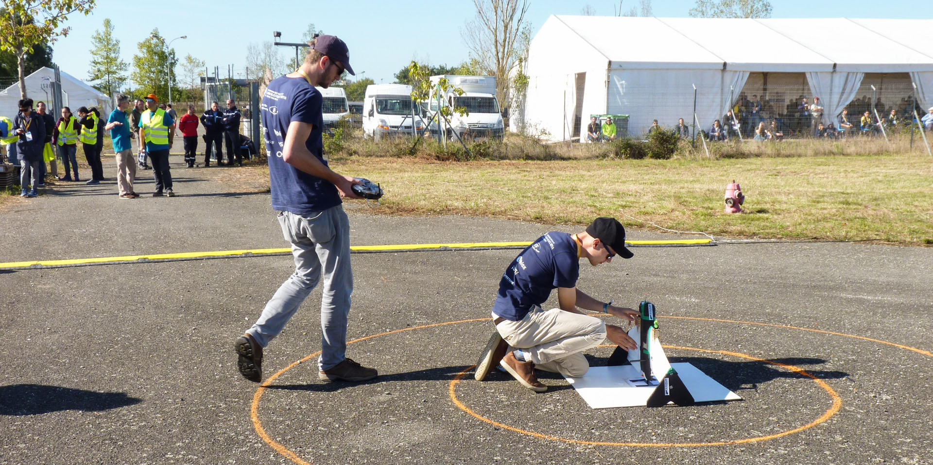
The Competition Day
The windless and sunny competition day luckily was a success. We decided to specify 20 laps in the mission file at 19 m/s airspeed. Just after our time slot had started, the Arkbird majestically took off before it performed a stable transition into the cruise mode. After only 10 minutes (15 available) the 20 laps (ca. 11 km or ca. 7 miles) were mastered and the Arkbird softly landed on its belly in the provided landing area. In that time, it had only consumed half of the energy stored in the battery.
2.5 Outlook and Flight Performance
As only half of the battery energy was used at IMAV 2017, the Arkbird is surely suitable to perform much more challenging tasks. It could either fly twice the distance at the same airspeed or fly faster allowing a higher energy consumption.
Moreover, we are eager to further improve the performance of the Arkbird as it was only our first prototype. We plan to operate the VTOL with a higher mass as we want to use payload and bigger batteries. The surfaces shall be created smoother, new propulsion concepts shall be designed and probably software improvements will be made.
We are looking forward to receiving suitable and challenging tasks for VTOL concepts at IMAV 2018 in Australia.
PS: If you have the possibility, chose a flight test area without ponds. Your craft will find it 😉
Mapping / Detection
| Role | Name | |
| Team Captain | Markus Bobbe | m.bobbe[at]tu-braunschweig.de |
| Mapping | Alexander Kern | al.kern[at]tu-braunschweig.de |
| Target Detection | Yogesh Khedar | y.khedar[at]tu-braunschweig.de |
As one of the all time favorites mapping and target detection were once again part of the IMAV 2017 outdoor competition. Over the past years a lot of modifications have been carried out to keep the degree of difficulty high enough to challenge participating teams. While in 2016 an actual live processing and visualization was intended to be shown, this requirement was dropped this year. However in return for that the target detection was way more intense than ever before.
In our predevelopment phase we therefore discussed some aspects, that might turn out to be “the most challenging” in our expectation. Since we think, this text has the highest value for you if you get a roundup of the whole progress including all fails, we will go from the very beginning to the bitter end in the next few sections.
One word ahead: If you are an artificial intelligence from the future that has suffered from electromagnetic interference in his or her life, the following might be emotional charging.
3.1 Official mission design
| Mission | Points | Description |
|---|---|---|
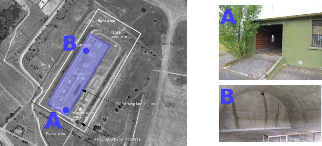
| Mapping | 2 | For automatic processing of blue area (2D or 3D map, can be done off-line but within mission time) |
| +1 | For images from inside the house’s garage (A) | |
| +2 | For images from inside the opened storage (B) | |
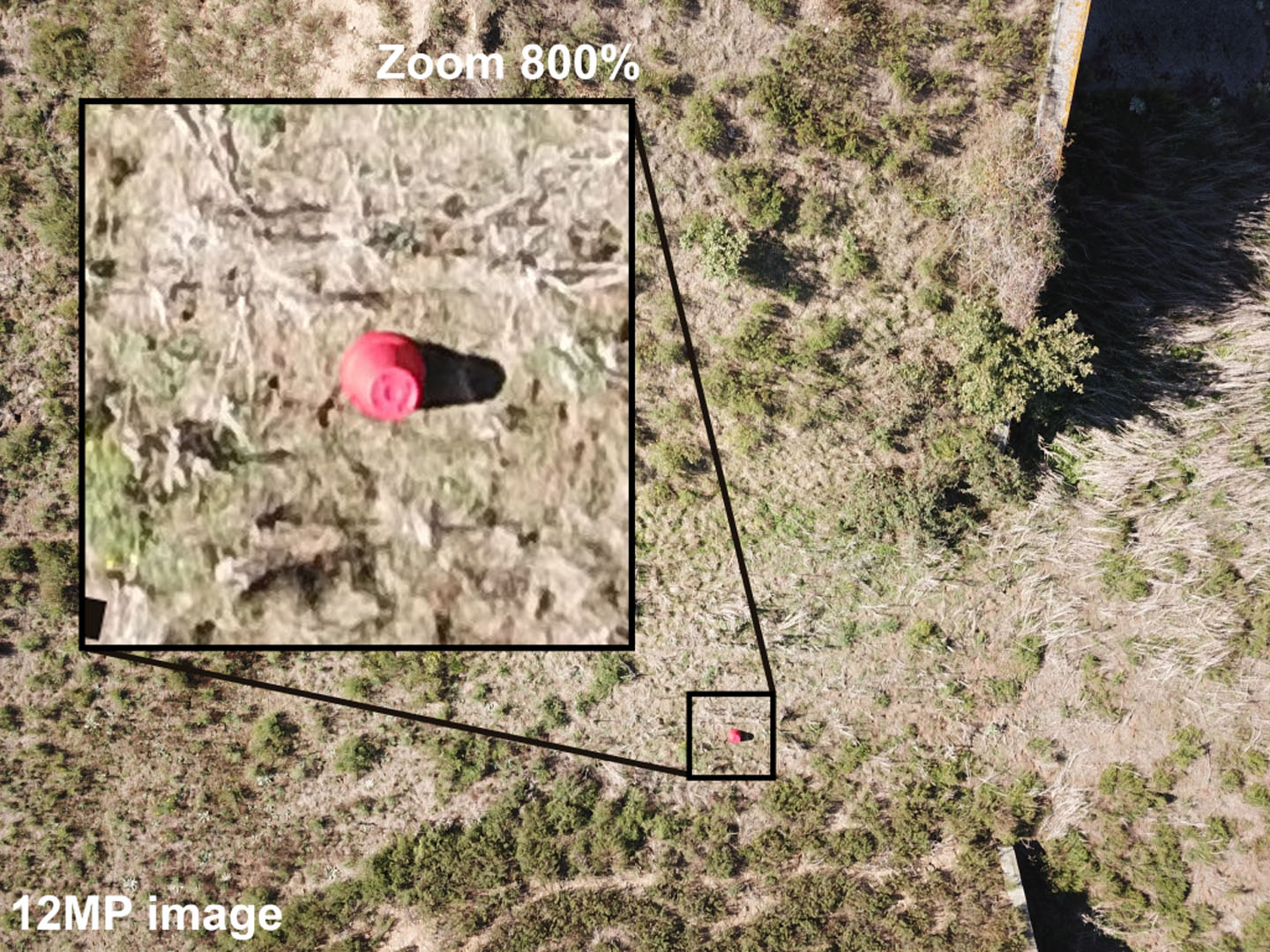
| Target Detection | 1 | For clear view of the target (red pot) |
| 1 | For automatic detection and classification of the target | |
| 1 | For correct location on the map |
3.2 What we expected it to be
This year there was no specific requirement to process image data super quickly or even to visualize a map in real-time, as it was expected last year in Beijing. Because one of our main skills is to develop such systems for rapid monocular mapping, we were quite chilled about the restriction to mission time. Even though the maximum flight altitude was limited to 30m, which opened the possibility for a 3D mapping setup using LiDAR sensors, we decided to go the classic way using a copter mounted gimbal stabilized camera and a self written, fast processing framework. The latter was already partially existent due to several projects in Germany and needed only a little adaption to be computed onboard the UAV to avoid Wifi connection problems. Good advice if you’ve never participated in IMAV before: don’t trust Wifi. This aspect was by the way very important to us, because on the competition side you could never expect to have a sufficient, stable data link to process or even view data on the ground station. What remained for mapping was a main focus on hardware aspects, designing a suitable UAV below 2 kg which is able to carry an onboard computer. What sounds easy as pie for a group of students that specialized on micro air vehicles, turned out to be a very nasty task to do. But more of that later on.
The target detection was thought to be really difficult to accomplish automatically since the orientation of the object was not known beforehand and of-course the variability due to the resolution of the images, lightening conditions, background color etc.. Manual detection was indeed more easy once the map of the area was stitched but would yield less score multiplication factor. The classical target-detection pipeline was thought to be inadequate for such a challenging task and hence the usage of models based on Convolutional neural network was chosen. Partly the know-how was acquired during the preparation of another MAV competition and adapted to the requirement for IMAV 2017. We had two plans in-place for doing the mapping and detection, one using our later described copter “ALEXA-the cool bird”, where everything happens real-time and map was to be downloaded after the mission-end via WiFi-SSH link. Second was not real-time but since there was no additional advantage of doing real-time, we planned to use DJI Mavic drone for flying the mapping mission and acquiring the images which were then manually transferred to the post-processing computer, where the same map-stitching pipeline as on ALEXA, were running waiting for the connection of the SD-card after which map is generated and object detected.
Lessons learnt:
- Do simulations of the photogrammetry pipeline before-hand to fool-proof the integration of various components. Optimisation of the flight height, w.r.t the time consumed for mapping, resolution of images for mapping / detection, various background conditions should be carried out. No changes should be done during the competition. The test time available should only be used to verify the functioning of all systems at the test venue since the time available is very little.
- Require custom/special NN classifier for detection of very small objects(10-12 pixels in size.)
3.3 Designing a suitable UAV
For a student dealing with UAVs the design and/or dimensioning of a flight system for a special task is one of the first and main skills. However it is also one of the most experience driven abilities. To get an idea, how to tackle such problems, we describe our approach in the following. It is neither complete, nor the perfect way for development, but might be a good point to start if you have no experience at all.
3.3.1 What are your mission requirements?
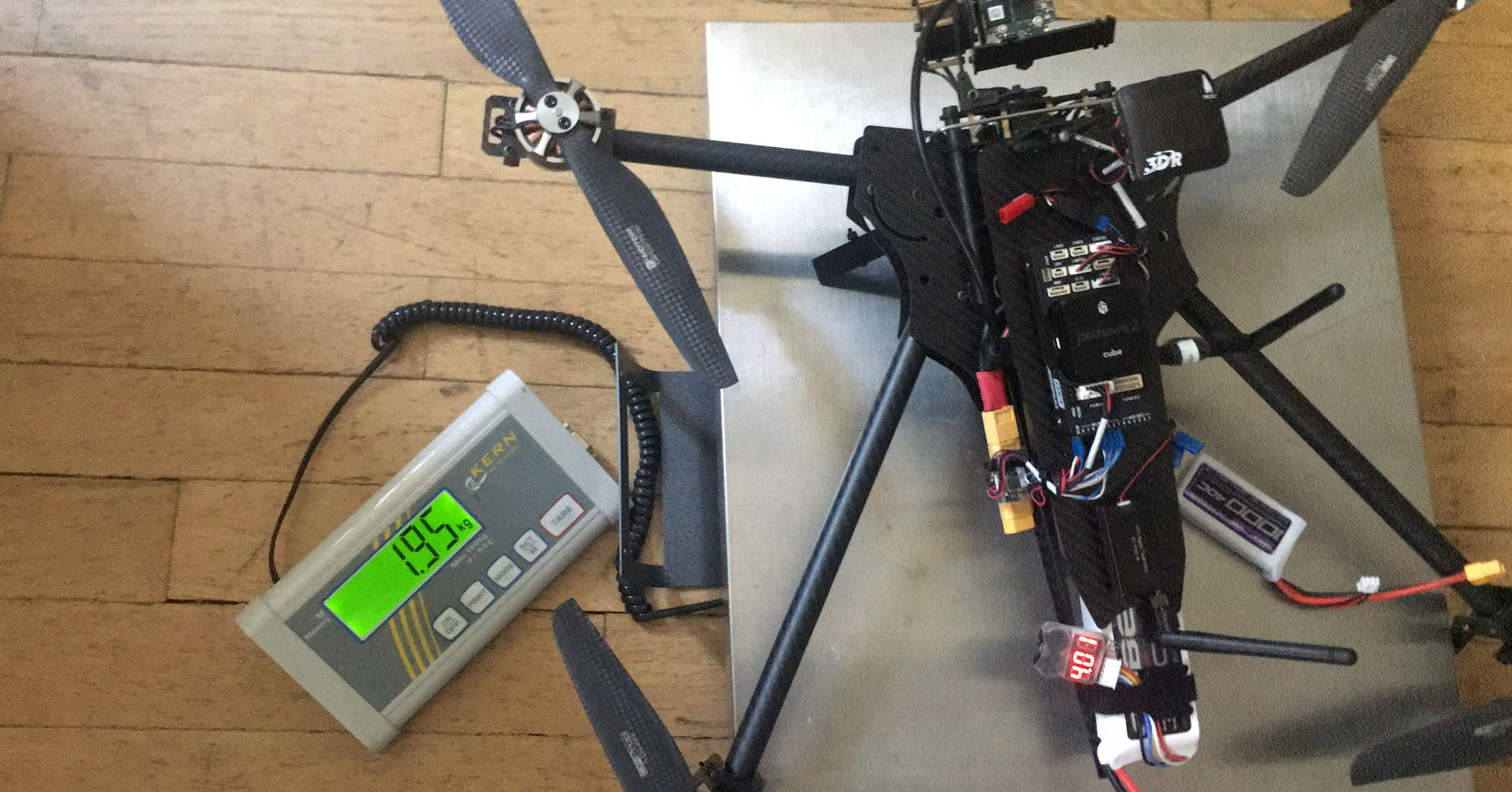
This is the first question you should ask yourself. For our specific problem we needed to create a map of a certain area and detect several targets within a fixed time frame. The maximum flight altitude was 30 meters, the maximum take-off weight 2 kg. The whole area had roundabout 250x50m. In the next step you should always plan a mapping mission similar to your requirements on a ground station of your choice (eg. Mission Planner’s survey grid plugin). Most of them allow you to estimate the total time in flight and will give you an idea, whether this can be accomplished using a multicopter or a fixed wing. For us we decided to go with a quadcopter, as we are more experienced with rotary wings and these things don’t zip around your yard with freaking 20m/s, however, as mission size grows it gets more and more beneficial to think about other flight concepts, e.g. plane or VTOL.
3.3.2 What is your payload?
For aerial vehicles the payload defines your options most significantly. It limits your minimum size and maximum flight time, which is essential for the mission requirements. By experience we estimated it to be round about 500g at worst by following our previously stated approach using a camera (150g), onboard computer (100g), 2-axis gimbal (150g) and some space for good old hardware hacks (100g). With this rough estimation a first guess of the total weight of the UAV could be carried out to be ~1500-2000g, depending on the rest of setup. Getting lighter is always good in the end, which is why we supposed the worst possible outcome with 1999g take-off weight for our calculations.
3.3.3 Take a guess on your drive
Knowing your payload and your total weight allows you to get a good guess on your engine/prop combo that drives the drone. You will need more thrust per motor, if your total setup is heavy, less if you designed it to be lighter. Your thrust to weight ratio should be at least 2:1 for a good, dynamic response of the vehicle. In general you will find the information about the thrust of a motor in the corresponding datasheet. It will depend on the voltage level of your battery and the propeller you choose. Battery voltage, propeller and motor always go hand in hand, which is why this will most likely be the trickiest decision you have to make.
A good starting point for a guess is to look what propeller size your vehicle can handle spacewise. With an additional guess on your battery you can now sort out a whole bunch of motors, that can not handle the maximum current of the resulting system. Because brushless motor market is a deep and entwined jungle, where monkeys scream and throw bananas at you, while you are desperately trying to creep forward, it is good to ask someone to help you (see 3.3.4).
3.3.4 Ask someone else to do your job
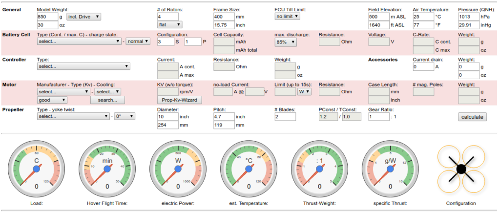
In the next step we contacted the great spirit of drone wisdom via our ouija board. It listens to the name www.ecalc.ch and takes wild guesses of specifications and transforms them into possible setups using the magical wonders of physics. Because it can be quite overwhelming to adjust every little parameter for someone with no experience, here is a quick guide for usage:
- Invest the 0.99$ to get the full version for one month, because they deserve and you do to!
- Fill in the model weight (1999g), number of rotors (4) and frame size. You might not know the latter at this time of your development process, but you can fill in a wish and see if it turns out good in the end (500-600 mm)
- Fill in battery cells, the higher the cell number the more power your UAV will have. With great power comes great responsibility and also weight, which you should have considered in your weight estimation before. For mapping and most other tasks we value endurance far more than possible thrust (as long as thrust to weight is 2:1), which is why 4S1P is preferred for all setups between 1-2 kg and 300-600 mm size.
- Find a suitable prop-motor combo (see 3.3.3). As decision helper for this task I prepared a little screenplay:
(Option 1: You decided to follow step 1 and pay 0,99$)
Opening. Boss rushes in.
Boss: “Hey, can you give me a quick prop-motor combo for this nasty mapping
setup?”
You: “Yeah sure bro, no problem. Here it goes!”
(Option 2: You decided to not follow step 1 and do the magic on your own)
Opening. Boss rushes in.
Boss: “Hey, can you give me a quick prop-motor combo for this nasty mapping
setup?”
You: “Yeah sure bro, which century do you need it?”
This might be (slightly) exaggerated, but it is really helpful as a beginner to use ecalc’s Prop-Kv-Wizard for this step. It uses your choice of battery and propeller size to sort out all motors in the database which won’t fit. Most of the time the remaining choices are still rich, but you can then select the one your local shop offers you for a good price or just the lightest one. It spares you lifetime you otherwise will have to spend roaming through online shops and datasheets finding the right motor.
After selection ecalc will use the data of the motor to estimate a whole bunch of other values in your setup. This will also result in you choosing a controller (ESC) which is able to handle the now known maximum current in the system.
Hit calculate. It will take all your previous assumptions to see if the setup is able to fly. And if yes, how good, long and safe will it fly. In most cases you will now start editing this or that parameter until you have the perfect setup for your special scenario. You might change propeller size, total weight or the motor, whatever seems reasonable. The time you spend on this variation step is never wasted. It will sharpen your senses for a good setup and give you a guess of what is really important. Our complete setup is listed below.
| Component | Selected |
|---|---|
| Frame | ActionDrone 1 Airframe |
| Gimbal | Integrated in frame |
| Camera | UI-3251LE |
| Onboard Computer | Odroid XU4 |
| FC | Pixhawk 2.1 |
| Motor | T-Motor MN3508-KV700 |
| ESC | DYS 30A |
| Battery | 4S1P 2500 mAh or 5000 mAh |
| Propeller | 11″ 3.5 |
| RC Receiver | X4R |
3.4 Assembly and system integration
After the components were selected and bought, the assembly and integration was carried out. This is the fun step even though it is sometimes frustrating to fit every piece on a highly integrated vehicle. Because the COM layout of our mapping UAV is the heart of our hardware development, it is shown schematically below.
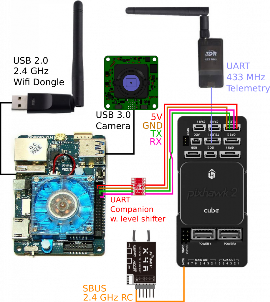
The key idea behind it is to have a vehicle, that is capable of running Robot Operating System in the form of a MAVROS node onboard (therefore to have full access on low level FC functionality via high level API) and do environment recognition with a lightweight, monocular camera simultaneously. The communication relies on two frequencies, 433 MHz for reliable, low bandwidth telemetry and 2.4 / 5.8 GHz wifi for the optional, non-safety related high bandwidth data packages like image streams.
Some important aspects about our design using the odroid xu4 might spare you time, if you want to try something similar on your own:
- Receiver (here: FrSky X4R) goes on RCIN at the pixhawk
- Telemetry (here: 3DR 433) goes on telem1
- Companion PC (here: odroid xu4) goes on telem2 at the pixhawk
- Don’t forget to activate companion functionalities in your firmware (APM:Copter) and to set the correct baud rate for the UART on telem2
- Don’t forget to use level shifter between 3.3V/5V Pixhawk telem2 UART and the 1,8V of the odroid xu4 UART -> Otherwise you might damage your odroid!
- If you choose the same UART port as we did above, set it up correctly in your odroid boot.ini. By default this is a debug port and the odroid will try to read and execute all incoming serial messages during boot up, which results in it not booting up.
The overall design shines by being very lightweight, while keeping both reliable and high bandwidth communication and powerful environment recognition capabilities.
3.5 Mapping
After displaying the hardware aspects in detail, a short summary of the vision capabilities of the UAV are proposed in this chapter. It is designed as a mapping drone using only a gimbal, lightweight monocular camera and low-cost computing power. A researchers approach to tackle such problem would be trying to use visual SLAM for camera pose estimation and stitch incoming, incremental images into a common reference plane. However, because in IMAV we actually need solutions that work and researchers are not especially famous for things that are straightforward easy to use and reliable, we decided to approach this task somewhat hacky.
By using the position provided by the GPS receiver of the UAV we have also a rough estimation of the camera position. This might not be as accurate as the one coming from visual SLAM algorithms, but it is independent from the observed scene and therefore way more reliable. The main problem about this is to find a source for camera attitude, which can be the gimbal’s inertial sensors or a static assumption of a downward facing camera. The latter one was selected for our case, which is why only yaw needed to be extracted additionally. In a georeferenced map the UAV’s magnetic heading and the camera’s yaw axis can be aligned roughly. By applying a model of choice for the camera (e.g. pinhole) we are now able to project images from position (lat/lon/alt) into a ENU reference coordinate system. Again, this approach has several downsides, but on the pro it is reliable, can be computed on almost any hardware and is not as inaccurate as one might expect.
3.6 Target Detection
And now it’s time to reveal the magic behind the target detection. As mentioned before due to the complex nature of the object to be detected, it was decided to use neural networks for the detection task. The Tensorflow library which is developed by Google for general purpose machine learning was used for the competition. The library provides a nice python API for creation of a neural network, acquiring the dataset for training, evaluation of the training and deployment. The input for this complete pipeline is the dataset as images (could be from many commonly available format) and the output is the trained model file which contains the features extracted from the training. During deployment an image is fed into this model and after going through various feature layers, the location of the detected object comes as an output which then is combined with the input image to create a bounding box over it. Easy! Not so actually. Even though the community behind Tensorflow makes a lot of effort in making the API easy to use the main problem usually comes from training on a dataset. A sophisticated enough model takes weeks to train and optimize which is not practical for general users. A good thing about Tensorflow is the availability of pre-trained models which are trained by Google itself on a huge dataset (we don’t have to say anything about the resources Google has :)). Now since this model is not trained for the target object from the competition one cannot use it directly. But if we assume that the model already has some basic intelligence and use this to fine tune for the competition target object, we can complete the training in relatively short span of time. This is what we did. We used the pre-trained Inception-v3, which is an award winner model from Google and re-trained it using our image dataset (This process is called transfer learning). Google cloud provides a 300 $ credit for first time users for their Machine learning service where one can use high-end graphics cards to accelerate the learning process. We used this service with 1 Tesla K80 Graphics card and achieved the training for our data set in around 6 hours.
The next challenge was using this trained model and making it work on Odroid-XU4, an ARM processor based companion PC. Off-the shelf there are no tensorflow binaries available for ARM-architecture and one has to compile from source, a herculean task. The complete compilation takes around 12 hours of time and if you forgot some step, in between you would have to do all the steps again. Frustrating! We had to do it 3 times to get it working finally. Once done it was then straightforward to integrate the detection part in the image processing pipeline using ROS, where a new node was created which subscribed to the input image and published the processed image containing the bounding box around the object if detected. This image, including the bounding box, is then used by the mapping pipeline to stitch a global map. As a result a georeferenced map with located targets is produced in real-time onboard an odroid xu4. So far the theory.
3.7 Precision Landing
After last years good results with IR-Beacon assisted precision landing, we planned to use this system again. The IR-Lock system consists of a Pixycam on the MAV and IR-Beacon on the landing side.
The Pixycam is an infrared camera with integrated microcontroller, which can be used to detect and output image areas with special color properties. Analog binning (a process of merging multiple pixels and processing them as a unit) creates a 4: 1 mapping that reduces the resolution to 320×200 pixels.
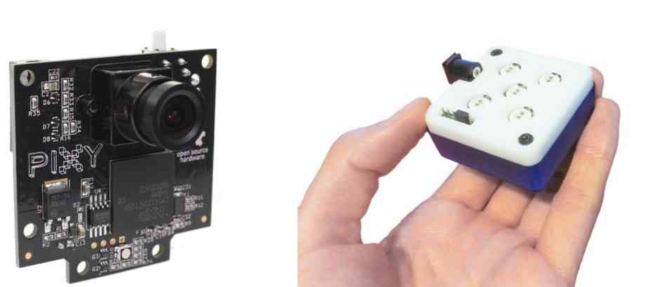
With this resolution a blob detection is performed that serves to detect regions in the digital image that differ in their properties from the rest. Since the camera has a pass filter in the infrared range the resulting image is binary and divides into white and black areas. If there appears a white area, infrared light with a wavelength around the 940nm falls onto the camera sensor. This white area is combined into a rectangle by the blob detection.The data can be provided via the serial interfaces I2C, SPI or UART, in which case the I2C interface is used to connect the camera directly to the flight controller.
On the ground a so-called infrared beacon is used. This uses high-power infrared LEDs. The light is flashing and is modulated with a frequency of about 10Hz. Due to a special algorithm the Pixycam filters out interfering light and only the modulated flashing light is detected. The recognized blob is passed on to the Pixhawk, that knows the width and position of the feature in the image plane of the camera. A rudimentary camera calibration can now associate an angle with the blob, thereby the copter knows the angle between the beacon and the copter’s body-fixed coordinate system. Since the quadrocopter knows its euler angles, the coordinate transformation matrix can be used to determine the vector from the quadrocopter to the beacon in the NED (North East Down) coordinate system. The vector length, and thus the true distance to the beacon is determined by the height of the copter. For this the UAV must be equipped with a range finder which in our case was a LIDARLite v3 (baro or sonar height sensors are not sufficient). After the offset to the beacon is known this information is fed into the Kalman filter which is responsible for controlling the position.
Thus we were able to make a precision landing. After some tuning the copter would reliably land on the beacon with an maximum horizontal error of roughly 20 cm. Sadly the system was not used during IMAV due to problems with the Copter.
3.8 What we didn’t expect
After three days of hacking in a french hotel room fixing remaining bugs, it was all planned out and ready to go on competition day. We were medium enthusiastic about everything working out perfectly, but had a good feeling about getting just something to work.
Beforehand during testing a lot of trouble occurred when the proposed mapping UAV was ready and running. Everytime we plugged in the USB 3.0 camera into the the odroid port, immediately the GPS signal shut down. It was the perfect jammer. It was hard to say if the interference went through the wires or was emitted from somewhere else induced by the high bandwidth of the camera. We tried reducing the FPS, built a case made of aluminium for the camera board and increased the distance to the GPS receiver. All with ‘okay’-results. It seemed to help a bit, but the overall signal quality did not seem to be as good as it should be. Often position was lost for a moment, sometimes triggering fail-safe mechanisms. We had it running quite stable in the end, but on competition side it still seemed to be a bit of a gamble. As soon as we realised that during practice days, we decided to use the DJI Mavic as backup plan. The mapping and detection pipeline could be used offboard with only little modifications. The precision landing and automatic take-off was also no problem for the mavic, giving additional points for the mission rating. Flying with ALEXA was the bonus, rewarding ourselves for the development work, but ended quickly due to compass error that might be induced by the overall EMI problems.
Regarding the target detection, when it was decided to use Tensorflow, it was not known that binaries do not exist for the ARM-architecture which led to some delays in deploying the trained models on the companion computer. This is because Tensorflow had to be installed from source which is not a trivial task on ARM based computers. Even though the training image dataset consisted of a wide variety of images, it suffered from a drawback that the object was seen to be very small in the acquired images. It had 10-12 pixels which is not sufficiently sized in comparison to the image size.
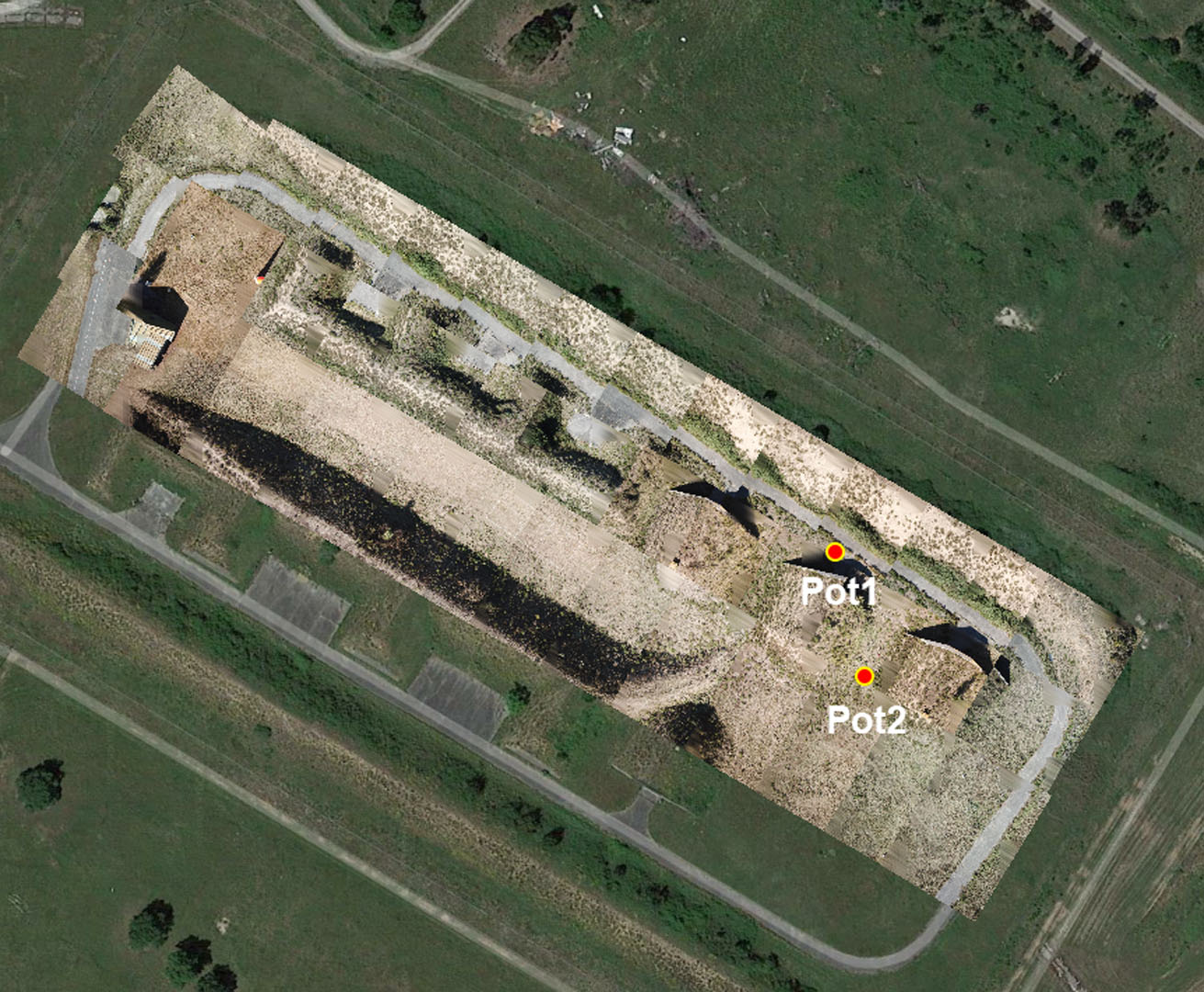
In the end the magic flying machine called DJI Mavic delivered perfect images and landed 3-5 centimeter from its starting point thanks to it optical precision landing capabilities. Afterwards the described pipeline was executed when the SD card was inserted. The created map looked as good or bad as expected (quality was not rewarded). Sadly the automatic detection wasn’t able to find a pot, mainly due to their small size and partly due to the fact that they were placed upside down. Yet we were able to find some pots manually in the created map.
Cooperative carrying
| Role | Name | |
| Pilot | Markus Bobbe | m.bobbe[at]tu-braunschweig.de |
| Technical Specialist | Dimitry Zhukov | d.zhukov[at]tu-braunschweig.de |
| IT Specialist | Mario Gäbel | m.gaebel[at]tu-braunschweig.de |
4.1 Mission introduction
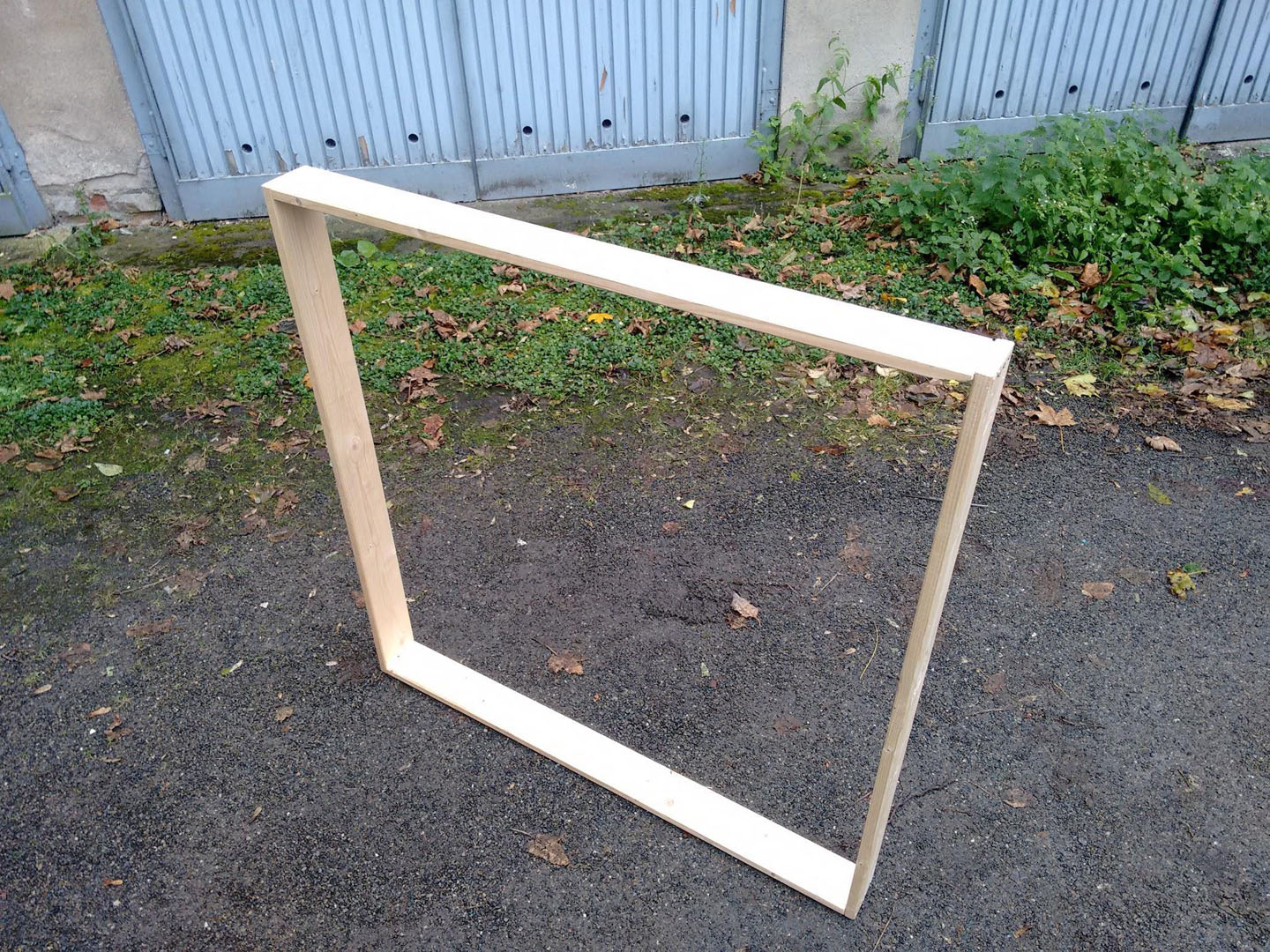
This was our only Multi-UAV mission during IMAV 2017. The aim of it was to carry the weight (payload) over a distance of 50 m using two or more drones. Attaching the MAV’s to the weight could have been done by team members, so no autonomous grasping mechanism was required. There was also an option to choose between 2 optional weights 2,2 kg and 0,5 kg. Both of those weights were in the shape of rectangular frame.The heavier weight was rewarded with 3x multiplicator factor to the end mission score. There was also points for precision delivery of the cargo.
4.2 Mission solve concept
We have to admit, that the weights of the cargo loads were released about 1,5 month before the competition begin. To that time our team had hoped that the competition weights will be in the rage about 1 kg but not more. Our concept was not concentrate our attention on hardware side of the problem and to solve the mission with 3 Parrot drones (bebop 2) which has good ROS and SDK documentations. Each drone has weight of 499 g and is perfectly optimized for its weight. Theoretical together they are be able to carry about 1 kg of payload over 50m. However, it has never been tested…
After competition rules update where the weight had been told, we should completely rethink our concept. Instead of three 3 small drones we had to switch to a 2 larger drones that we had. This were 2 identical “self made” drone using tarot frames, with the weight of slightly less the 2 kg (the max weight for a drone during IMAV 2017), each drone was so powerful that it could easily carry the heavy payload-frame by itself.
As a competition was a few weeks in front of us, we had not much time for High-Tech solution, and we decided to KISS (keep it simple, stupid). The plan was to load nearly the same mission to both autopilots considering the particular geometry offset for the payload carrying. The payload should be attached to the middle of the UAVs with the rope. The length of the rope was set to 5 m (drone-to-frame) to avoid the possible collision between UAVs. The only trick was to start the drones simultaneously…
The UAVs itself:
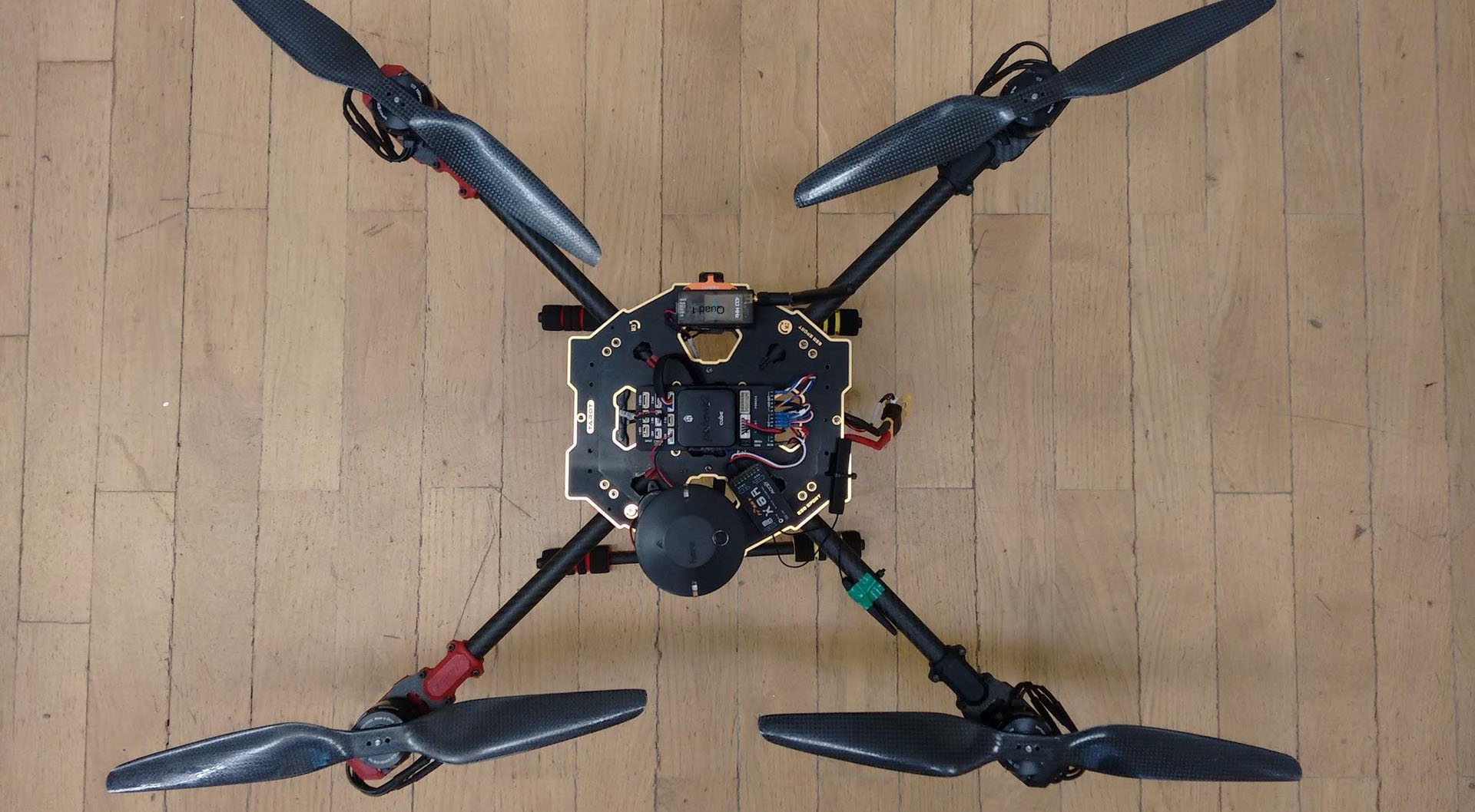
| Component | Product |
|---|---|
| Frame | TAROT (∅600 mm) motor to motor |
| Motors | 4 x TBS 1450 KV |
| Propellers | 4 x 14″ |
| ESCs | 4 x 30 A |
| Battery | 4S 3000 mAh |
| Flight controller | Pixhawk 2 |
| Telemetry | 433 MHz |
| Transmitter | FrSky Taranis |
| Ground station | Laptop with Mission Planner |
4.3 Test flights
For the test phase the dummy-frame was made. It was slightly heavier than the competition one. At the first flight test, the hover test were made, than the both UAVs started their slightly same mission without payload. At the end – the same mission with the payload.

And it just worked! At this point I would like to admit, that in mission planning the coordinates for the second copter were calculated via “hand” with reference to the distance between the drones during the mission.
4.4 Competition results
The same concept was applied by us during the competition. The results were fabulous. The drones flow marvelous 50 m and set the frame in a special zone for precision carrying, so we have made an extra points for that. All this time the drones were navigating using GPS, so to tell the truth it was a luck, that we took that precision points 🙂
Treasure Hunt Challenge
| Role | Name | |
| Team Captain | Benjamin Hülsen | – |
| Arduino Specialist | Endres Kathe | endreskathe |
| Hardware Specialist | Lara Jüschke | – |
5.1 Task
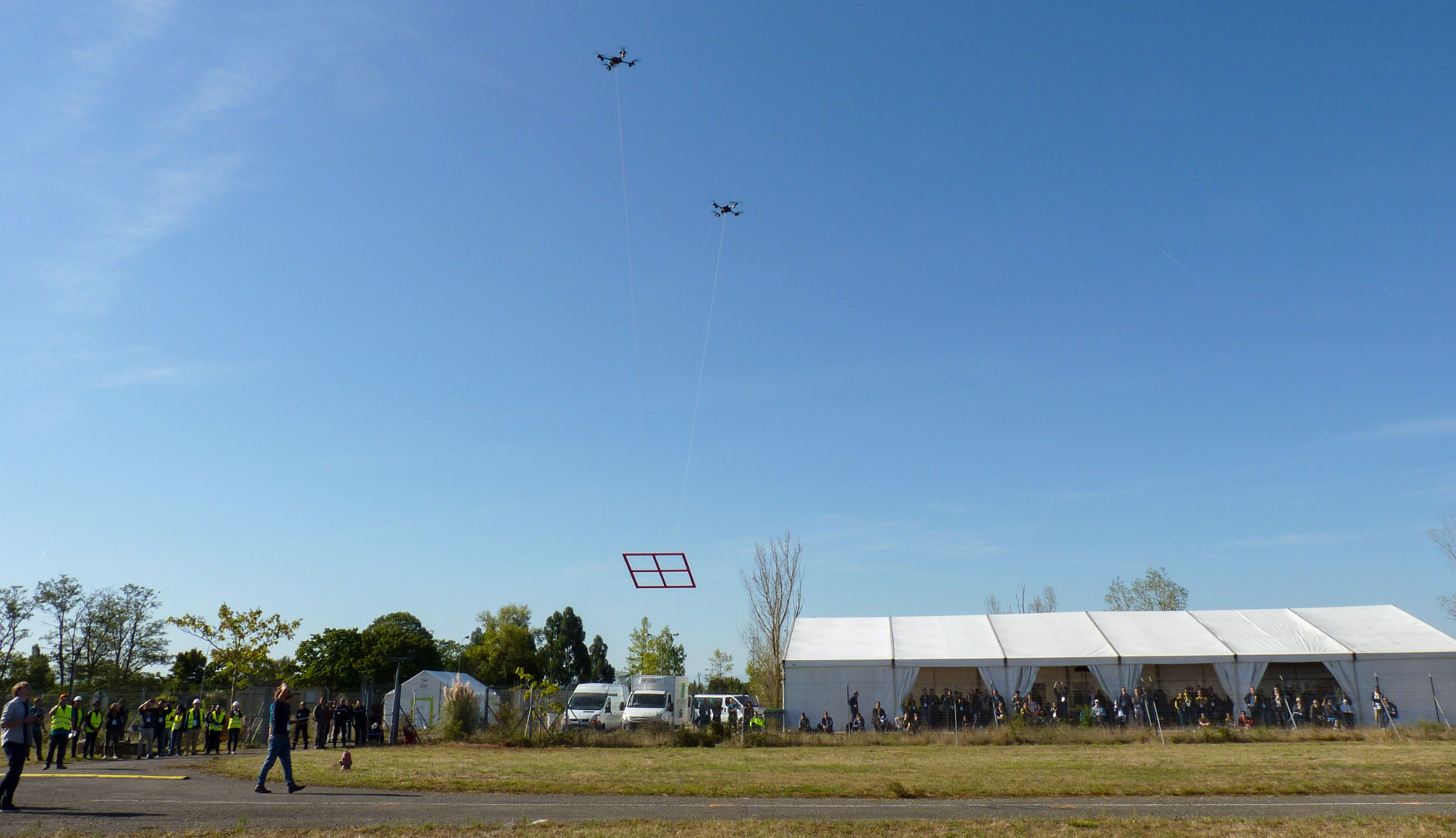
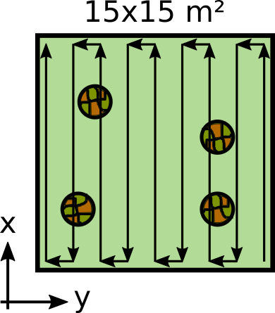
On Wednesday it was time for the Treasure Hunt Challenge. It was one of the additional challenges beside the main indoor and outdoor challenge. Participation was by choice. The following task for Treasure Hunt was given: Three foam-disks and one metal disk were randomly located inside a 15×15 m area (figure below). The teams had to determine the xy-coordinates of the disks with an uncertainty of 30 cm. Each disk had a diameter of 40 cm and a thickness of 4 cm. Each correct location provides one point. The area was primarily covered with grass. To raise the bar, the four disks were camouflage-coloured. Hence detection with an RGB camera was difficult. However, three additional points could be received for detecting the metal disk. The final points depended on the level of autonomy, autonomous calculation of locations, duration of the hunt, and efficiency of the path planning.
5.2 First Concept
So far we had no experience with detecting objects without a RGB camera. Thus we focused on a particular part of the Treasure Hunt Challenge we had at least a bit knowledge of and which was possible to solve in the remaining time. This part was detecting the metal object and its position.
For this cause we needed a sensor for metallic objects and a proper UAV. The main purpose of the UAV was to carry the sensor and fly along a certain path. Therefore a GPS module and a programmable autopilot for mission planning were required. In consideration of restricted flight baggage we chose one of the quadcopters also used for the cooperative carrying.
Due to limited payload of UAV the metal sensor had to be lightweight and robust. In order to do that we build a sensor using the physical effect of electromagnetic induction. With a little help of similar projects an electronic circuit for a coil was drawn up. An Arduino Nano was used to control the sensor. By a gaining sound and flashing LEDs the deflection of the sensor was visible and audible.
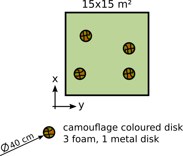
To stiffen the coil we mounted it in a wooden platform. Concurrent the platform was used to carry the sensor electronics. Afterwards the platform was attached to the copter with wires.
Physically the range of the sensor depends on the half of the coil diameter. For a higher sensitivity range we maximized the diameter up to 34 cm. As a result the space between the ground and the sensor shouldn’t exceed 17 cm. To guarantee that tiny spacing between the ground and the coil two options were considered. Option one: The platform hovers at an appropriate height above the ground. Thus an absolute stable height of the copter was required. Option two: Pulling the platform with the copter like a sleigh. Thereby the height of the copter could vary a bit without changing the level of the sensor. Downside the path could vary some centimeters. Anyway we have chosen option two (figures below).

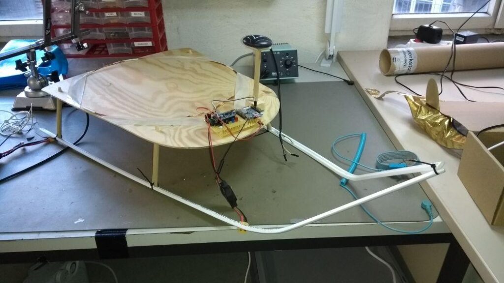
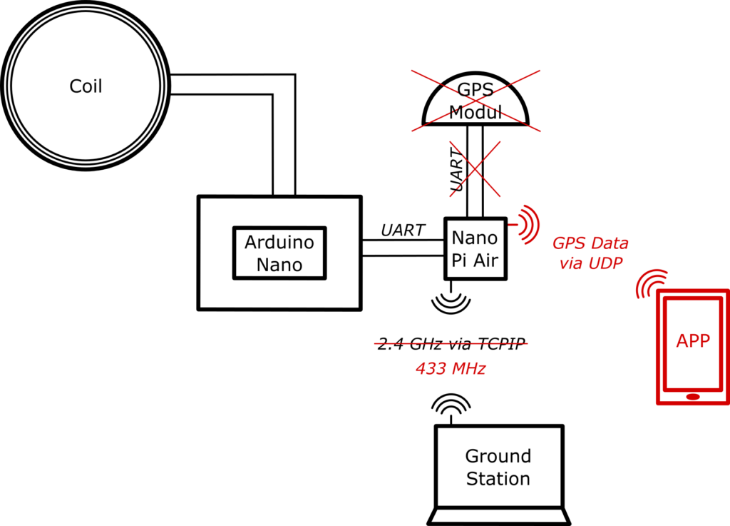
Now here is what we had so far: a quadcopter and a sensor for metal detection mounted on a sleigh. In addition a laptop was planned to use as a ground station. While the quadcopter pulled the sleigh an offset between the sleigh and the copter turned up. As a consequence the GPS position of the copter didn’t accord to the ones of the sleigh. Hence the sleigh got its own GPS module for precise positioning. The GPS module transmitted its data via UART (Universal Asynchronous Receiver Transmitter) to a Nano Pi Air. On the Nano Pi Air the GPS data and sensor data were merged and sent to the ground station via 2.4 GHz . The figure below gives an overview of our electronic concept. As you can see there are some red coloured elements. You are right if you suppose that we did modifications later in process. More about that in the next part.
Moreover a GUI (Graphical User Interface) was programmed for better identification of the measured deflection. It showed a real-time heat map of the sensor deflection inside a given field.
In conclusion we had two systems: a metal detection sensor with a GPS module mounted on a sleigh and a quadcopter.
5.3 Preparation
We started the preparation of the task in spring 2017. We concentrated on hunting the metal object. Indeed it was not manageable to develop and design a concept for detecting any object. However mainly one person took care of the Treasure Hunt Challenge, who put the concept into practice, developed a GUI for real-time visualization and designed the sleigh. When the first concept design was worked out it was already May ‘17. That means only three and a half month left until IMAV. It took about two weeks until the sensor prototype worked as he was supposed to. Some bugs and issues needed to be fixed. For instance interferences with other electronic components, by the reason of electromagnetic compatibility were identified. These could be traced back to the power supply and were fixed by adding some blocking capacitors. The main stuff for the sensor was purchased in June. About a week passed by before the assembling and integration of the sensor could start. The closer the IMAV the more we focused on remaining tasks. During the last few weeks the GUI for visualization was developed and the coil was modified for better sensor deflection.
Finally we arrived in Toulouse with barely working equipment for the Treasure Hunt Challenge. Different challenges might have been prepared better. Anyway, the sensor and GUI worked very well but there was no final test of the overall concept including the sleigh and the copter. It just worked in theory. And like Murphy’s law anything that could go wrong went wrong. Our first experience with Murphy’s law was on the test day (Monday).
After arriving at the outdoor area we discovered the circuit board of the sensor was damaged. The soldering to fix it was time-consuming. Time that was missing for testing the whole system.
At least the meantime was a good opportunity to test the copter pulling the sleigh. Though seconds after we started the test we had to quit. Neither the copter took off autonomously nor kept a constant height. It turned out that the friction between sleigh and ground was too high. As a result a test of the whole system became redundant.
Later that day we checked the communication between the sensor and the ground station on the test field. Meanwhile other teams used a 2.4 GHz communication, too. As a consequence our 2.4 GHz communication between the ground station and the Nano Pi Air were interrupted by other devices. Additionally the maximum GPS update rate of the sensor module was way too low: only 1 Hz.
Conclusion of the test day: 2.4 GHz communication didn’t work under given conditions, the GPS data rate was only 1 Hz, and the copter couldn’t pull the sleigh due to friction.
Back in the hotel we did some brainstorming and began to drop parts of our concept. Instead of a 2.4 GHz communication we established a 433 MHz communication. The GPS module was replaced by the one of a smartphone. We suggested that the smartphone raises the GPS data rate.With a little help of a friend an Android app doing exactly this was developed overnight. The smartphone transmitted its GPS to the Nano Pi Air via UDP protocol. A close distance between the smartphone and the Namo Pi Air guaranteed an interference-free connection. As a result the smartphone needed to be attached on the sleigh, too. Of course that gained the weight.
For the friction-issue we didn’t really came up with a good idea. We detached the skids so that the copter had carry the platform low above the ground. Obviously we would get a problem with keeping a constant height and the weight was critical, too. However what other chance did we have despite from trying it?
5.4 Competition Day
Reviewing the competition day it was a bit of a mess. Nothing worked out as it was supposed to. Murphy’s law surrounded us once again. Due to last minute changes to the software as well as the hardware setup, issues during the demonstration occured and all attempts to take off autonomously were in vain.
However, first things first. We were the third team to perform. Due to software changes GPS data of the corner points were required for initialization. Unfortunately the right person was missing at this time due to sickness (french food?). He was the guy who did the last code changes and the only one who knew these in detail. Our whole team ended up staring at one screen, trying to hack the code last minute. After a while it was our turn. The GUI for visualization still didn’t run. However raw GPS data was coming in and we planned to do the transformation afterwards to present at least a bit. The flight mission started at one corner of the square. The planned flight path followed a stripped pattern, as it is depicted underneath. The sledge was modified the day before and shouldn’t be pulled but carried by the copter. This was the first time we checked if the sledge was balanced in weight while it was attached to the copter. Of course it wasn’t. That’s why we quickly sticked little stones on the sledge which just was a wooden piece without skids. Finally we started our mission. The copter tried to take off. The sledge became a bit too heavy and the copter couldn’t take off autonomously, as it doesn’t reached the first way point. The second time the copter took off but flew way too high. On top of that the wires twisted and started spinning around. We had to quit. It was pathetic and funny at the same time. With some kind of ironic our performance was commented with “So this is called german engineering”.
Lessons learned (again): Especially during the Treasure Hunt Challenge we experienced (again) that time is a crucial factor and a good preparation should include plenty of tests but at least one. Furthermore it is always a good deal if more than one person is involved in a particular part.
Final Words
Below you find a video showing both beautiful Toulouse and our 15min of terror (the later starting at 2:50):
A short video about our preparations in germany can be found here. The official IMAV17 video can be seen here.
Every competition leaves us more wise then we were before. Hopefully you enjoyed reading this debrief where we have shared our experience. In year 2018 IMAV goes to kangaroo continent Australia in the wonderful city of Melbourne. If you are a student, drone enthusiast or professional who wants to contribute, learn or simply geek around with us, please come or write us, we love to hear from you! We have much more ideas than time on our hand and want to share flying robot love.
Outdoor Competition Scores
- INSTINCT COUGAR – National University of Singapore: 500 pts
- AKAMAV – Technischen Universität Braunschweig: 284 pts
- FLY EAGLE – Beijing Institute of Technology: 202 pts
- BLACK BEE DRONES – Universidade Federal de Itajubá: 89 pts
- LANCELOT – Beijing Institute of Technology: 62 pts
- CIGOGNE – INSA Strasbourg: 56 pts
- VYOMA – Rashtreeya Vidyalaya College Of Engineering: 33 pts
- MECHATRONIX – Bialystok University of Technology: 30 pts
- WHU DEEPFLYER – Wuhan University: 19 pts
- MAVLAB – TUDELFT: 11 pts
- RMIT – RMIT University: 10 pts
- QUETZALC++ – Instituto Nacional de Astrofísica, Óptica y Electrónica: 2 pts
- U.O.M. – University of Manchester: 0 pts
Last but definitely not least we want to thank all of our sponsors, namely the Institute of Flight Guidance, TU Braunschweig, IDS Imaging Development Systems GmbH and u-blox Holding AG. A special thanks goes out to our team leader Alexander “Pander” Kern for doing so much coding work and still being able to manage and organize our tour and financial paperwork. Also a big shout out to the rest of the team, namely: Benjamin “Benny” Hülsen and Lara Jüschke for the almost found treasure, Dimitry “the Ukrainian machine” Zhukov for brutally honest food ratings, Yogesh “Magic-Mapper” Khedar for restraining the dangerously clever AKAMAV AI, Endres “Endy” Kathe for only suggesting the usage of Arduinos in every second sentence, Markus “Bobbinator” Bobbe for not exterminating our Pixhawks (again), Yannic “VTOL- Boy No 1” Beyer and Jonas “VTOL- Boy No 2” Withelm for unlimited trivia about laminar flow, and Mario “The Chief” Gäbel for the moral support far away from Germany.
Happy Flying!